© 2000-05 PRINTED IN JAPAN
B51-8536-00(S) 200
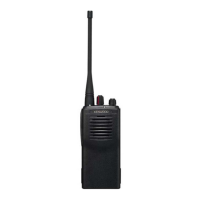
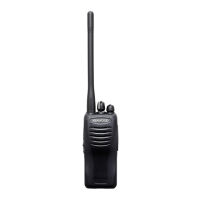
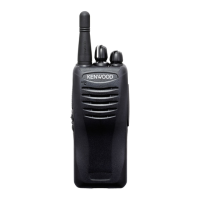
VHF FM TRANSCEIVER
TK-2107
SERVICE MANUAL
GENERAL.................................................................. 2
REALIGNMENT......................................................... 2
DISASSEMBLY FOR REPAIR................................... 4
CIRCUIT DESCRIPTION ........................................... 5
SEMICONDUCTOR DATA ......................................... 9
DESCRIPTION OF COMPONENTS........................ 10
PARTS LIST............................................................. 11
EXPLODED VIEW ................................................... 17
PACKING ................................................................. 18
ADJUSTMENT......................................................... 19
PC BOARD VIEWS
TX-RX UNIT (X57-6020-21) ................................ 23
SCHEMATIC DIAGRAM .......................................... 27
BLOCK DIAGRAM .................................................. 31
LEVEL DIAGRAM ................................................... 33
KNB-15A (Ni-Cd BATTERY) ................................... 34
SPECIFICATIONS ................................BACK COVER
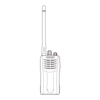
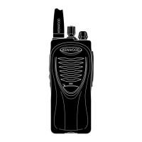
Antenna
(T90-0733-05):M3
Cabinet assy
(A02-2448-13)
Knob(VOLUME)
(K29-5255-03)
TK-2107 (16 channels)
CONTENTS
Knob
(CHANNEL SELECTOR)
(K29-5278-03)