Do you have a question about the Kenwood TK-2107G and is the answer not in the manual?
Safety precautions for operating and servicing the equipment.
Steps for setting up the transceiver, including programming.
Overview of PC programming requirements using computer, interface, and software.
Steps to connect the transceiver to a PC using interface cables or USB adapters.
Step-by-step guide to remove the transceiver's case assembly from the chassis.
Instructions for detaching the TX-RX unit from the transceiver chassis.
Details the PLL circuit's role in generating local oscillator and RF signals.
Describes the VCO output amplification to the final RF power amplifier stages.
Details the Automatic Power Control (APC) circuit for stabilizing output power.
Pin assignments and functions for the microcontroller (IC403).
Description of components within the TX-RX unit (FETs, Diodes, LEDs, etc.).
Continued list of components for the TX-RX unit.
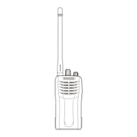
Diagram showing the physical arrangement of parts in the transceiver.
Lists the test equipment needed for transceiver alignment procedures.
Adjustment procedures common to both transmitter and receiver sections (VCO).
Adjustment procedures for the receiver section.
Adjustment procedures for the transmitter section.
Procedure for adjusting transmit power output via PC mode.
Diagram showing the component layout on the TX-RX unit's component side.
Diagram showing the component layout on the TX-RX unit's foil side.
Schematic diagram for the TX-RX unit.
Block diagram illustrating the main functional blocks of the transceiver.
General specifications of the TK-2107G transceiver.
| Brand | Kenwood |
|---|---|
| Model | TK-2107G |
| Category | Transceiver |
| Language | English |