Do you have a question about the Kenwood TK-940 and is the answer not in the manual?
Lists recommended precautions for user safety.
Covers vehicle inspection, antenna, radio mounting, and power wiring.
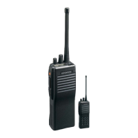
Details features available for trunked transceiver operation.
Details features available for conventional transceiver operation.
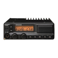
Explains the functions of the front panel push buttons.
Explains making telephone interconnect calls using AUTO TEL.
Details talk-around, transmit disable, busy lockout, and scanning.
Introduces programming setup using PC, interface, and software.
Details the system display, group display, and various indicators.
Provides detailed explanations of various operating features.
Covers KDD-4 features: audio mute, call indicator, and scan operation.
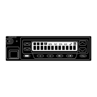
Details panel tuning mode and controls (SYSTEM, GROUP, AUX, SCAN, Volume).
Explains system scan, fixed/user lockout, and delay times.
Explains clear-to-talk operation modes (ON/OFF).
Details the installation and assembly of the KDD-4 DTMF decoder.
Guides on installing the KDD-4 into the transceiver unit.
Details connecting and modifying the transceiver for KCT-18 ignition function.
Details connecting KES-3 and KES-4 external speakers.
Guides on installing the KCT-19 accessory connection cable.
Details the transmitter system including microphone amp and final amp.
Explains the PLL unit's operation, components, and unlock detection.
Details control unit functions, memory, shift register, and D/A converter.
Provides terminal connection diagram and function list for the microprocessor.
Provides terminal connection diagram and function list for the LCD Assy IC2 microprocessor.
Provides terminal connection and block diagram for the PLL/VCO IC.
Lists components for the TX-RX unit (TK-940/TK-941).
Lists capacitors and resistors with their specifications and dimensions.
Lists terminal functions for TX-RX unit connectors (CN1, CN2, CN3, CN4, CN5, CN6, CN201, CN203, J1, J2, J3, J201).
Shows component and foil side views of the TX-RX Unit (B/2).
Shows component side view of TX-RX Unit (A/2).
Shows foil side view of TX-RX Unit (A/2).
Shows foil side view of TX-RX Unit (B/2).
Shows the schematic diagram for the TX-RX Unit (A/2).
Shows the schematic diagram for the TX-RX Unit control section (B/2).
Lists general, receiver, and transmitter specifications per EIA standards.
| Brand | Kenwood |
|---|---|
| Model | TK-940 |
| Category | Transceiver |
| Language | English |