EasyManua.ls Logo

Kenwood TK-980 Service Manual

Kenwood TK-980
62 pages
To Next Page IconTo Next Page
Page #1 background imageLoading...
Page #1 background image
© 2001-9 PRINTED IN JAPAN
B51-8588-00
(
N
)
1016
800MHz/900MHz FM TRANSCEIVER
TK-980/981
SERVICE MANUAL
GENERAL ................................................................. 2
OPERATING FEATURES ......................................... 3
REALIGNMENT...................................................... 13
INSTALLATION...................................................... 16
CIRCUIT DESCRIPTION......................................... 25
SEMICONDUCTOR DATA..................................... 29
DESCRIPTION OF COMPONENTS ....................... 30
PARTS LIST ............................................................ 32
EXPLODED VIEW .................................................. 41
PACKING ................................................................ 42
ADJUSTMENT ....................................................... 43
PC BOARD VIEWS
PLL/VCO (X58-4530-XX) .................................. 50
TX-RX UNIT (X57-6520-XX) (A/2) ................... 51
TX-RX UNIT (X57-6520-XX) (B/2).................... 57
SCHEMATIC DIAGRAM ........................................ 61
BLOCK DIAGRAM.................................................. 69
LEVEL DIAGRAM................................................... 72
TERMINAL FUNCTION ......................................... 74
SPECIFICATIONS................................................... 75
CONTENTS
Microphone
(T91-0621-05)
Cabinet (Upper)
(A01-2165-23)
Panel assy
(A62-0991-03)
Key top
(K29-5284-02)
SUPPLEMENT
This service manual applied to products with 30600001 or subsequent serial numbers.
In terms of the products with the serial numbers earlier than 30600001, refer to the TK-980/981 service manual as per
part No. B51-8478-10.

Other manuals for Kenwood TK-980

Question and Answer IconNeed help?

Do you have a question about the Kenwood TK-980 and is the answer not in the manual?

Kenwood TK-980 Specifications

General IconGeneral
BrandKenwood
ModelTK-980
CategoryTransceiver
LanguageEnglish

Summary

GENERAL

INTRODUCTION

Defines the scope and intended audience of the service manual.

PERSONNEL SAFETY

Provides essential safety precautions for personnel during operation and servicing.

PLANNING THE INSTALLATION

Covers crucial steps for planning radio installation, including location and wiring.

OPERATING FEATURES

Operation Features

Overview of the transceiver's capabilities and modes of operation.

Transceiver Controls and Indicators

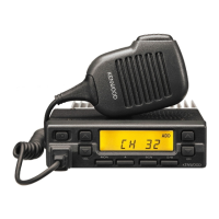
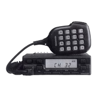
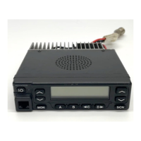
Details on front panel controls, indicators, and programmable keys.

Front Panel Displays and Indicators

Explanation of the various displays and indicators on the front panel.

System Scan

Describes how to use and configure the system scan function.

Time-out Timer

Details the function and configuration of the time-out timer.

Horn Alert

Explains the horn alert function for notifications.

Selective Call (SELCALL)

Covers the selective call feature for individual or group communication.

Emergency Function

Details the emergency transmission and response features.

Audible User Feedback Tones

Lists and describes the various audio tones used for user feedback.

INSTALLATION

Accessory Connection Cable (KCT-19)

Instructions for installing the KCT-19 accessory connection cable.

Data Equipment Connection

Details on connecting data equipment and configuring jumpers.

Ignition Sense Cable (KCT-18)

Instructions for installing and using the KCT-18 ignition sense cable.

Interface Cable (KCT-31)

Information on the KCT-31 RS-232C interface cable.

PA/HA Unit (KAP-1)

Details for installing and modifying the KAP-1 unit for PA/HA functions.

External Speaker

Instructions for connecting external speakers (KES-3, KES-4).

CIRCUIT DESCRIPTION

Frequency Configuration

Explains the frequency synthesis and double-conversion system.

Receiver System

Describes the RF signal path and processing in the receiver.

Transmitter System

Details the stages involved in amplifying and transmitting the signal.

Control Circuit

Explains the functions of the CPU and its control over various circuits.

Encode

Describes the signal processing for encoding data and modulation.

Decode

Explains the signal processing for decoding received data.

Power Supply Circuit

Details the power supply circuit, including protection and timed power off.

SEMICONDUCTOR DATA

Microprocessor : 30622M8A-4F9GP (TX-RX Unit (B/2) IC511)

Pin assignments and functions for the main microprocessor.

Terminal function

Lists the terminal functions for the microprocessor pins.

DESCRIPTION OF COMPONENTS

TX-RX Unit (X57-6520-XX) (A/2)

Lists components and their functions on the A/2 TX-RX unit.

TX-RX Unit (X57-6520-XX) (B/2)

Lists components and their functions on the B/2 TX-RX unit.

PLL/VCO (X58-4530-XX)

Details components related to the Phase Locked Loop and Voltage Controlled Oscillator.

PARTS LIST

CAPACITORS

Lists capacitor types, values, and specifications.

RESISTORS

Lists resistor types, values, and specifications.

TX-RX UNIT (X57-6520-XX)

Component parts list for the TX-RX unit.

PLL/VCO (X58-4530-XX)

Component parts list for the PLL/VCO section.

EXPLODED VIEW

PACKING

ADJUSTMENT

Test Mode Operating Features

Describes how to enter and use the transceiver's test mode.

Tuning Mode

Details the tuning procedures for various parameters.

Test Equipment Required for Alignment

Lists the necessary test equipment and their specifications for alignment.

Receiver Section

Provides adjustment procedures for the receiver section.

Transmitter Section

Provides adjustment procedures for the transmitter section.

PC BOARD VIEWS

PLL/VCO (X58-4530-XX)

Component and foil side views of the PLL/VCO board.

TX-RX UNIT (X57-6520-XX) (A/2)

Component and foil side views of the TX-RX unit (A/2).

TX-RX UNIT (X57-6520-XX) (B/2)

Component and foil side views of the TX-RX unit (B/2).

BLOCK DIAGRAM

LEVEL DIAGRAM

Receiver Section

Illustrates signal levels within the receiver section.

Transmitter Section

Illustrates signal levels within the transmitter section.

TERMINAL FUNCTION

CN7, CN502, CN101 Terminal Functions

Details terminal functions for CN7, CN502, and CN101 connectors.

CN501 Terminal Functions

Lists terminal functions for the CN501 connector.

J501 Terminal Functions

Lists terminal functions for the J501 connector.

SPECIFICATIONS

GENERAL

General operating specifications including frequency range and power.

RECEIVER SPECIFICATIONS

Receiver performance specifications according to EIA/TIA-603.

TRANSMITTER SPECIFICATIONS

Transmitter performance specifications according to EIA/TIA-603.

Related product manuals