Do you have a question about the Kenwood TK-880 and is the answer not in the manual?
Manual overview, safety precautions, and installation planning guidance.
Guidance on vehicle inspection, antenna, radio, and DC power wiring.
Factors and dealer assistance for antenna system selection.
Selecting a convenient location for the control station radio.
Overview of 5-tone and DTMF/2-tone/DMS model capabilities and programmable features.
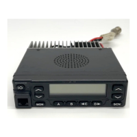
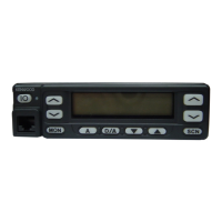
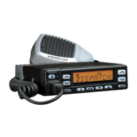
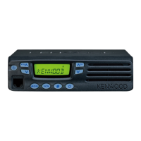
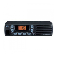
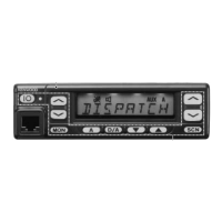
Description of front panel controls, keys, and indicators on the transceiver.
Transmitting stored DTMF codes automatically and programming them.
Activating emergency mode, jumping to programmed emergency channel.
Function for changing volume levels of tones and AF volume.
Functionality of the Monitor key for DTMF/2-tone/DMS and 5-tone systems.
Temporary monitoring of squelch and carrier presence.
Switching between user-selectable tone pairs for encode/decode.
Amplifying microphone audio for external speaker output.
Managing call queue buffer and related functions.
Setting and using a password for transceiver security.
Entering Selcall codes for receiving specific transmissions.
Activating and deactivating the channel scanning function.
Temporarily modifying the scan list by adding or deleting channels.
Enabling or disabling the voice scrambler function.
Entering Selcall codes for initiating calls.
Accessing and selecting Selcall codes from a programmed list.
Combined entry mode for Selcall and Status information.
Combined list mode for Selcall and Status information.
Manually sending GPS location data.
Enabling access to functions combined with the Shift key.
Adjusting the squelch sensitivity level.
Temporarily unmuting the squelch while key is pressed.
Permanently disabling the squelch.
Inputting and transmitting status information to the base station.
Selecting status codes from a list for display or transmission.
Direct communication on receive frequency without repeater.
Transferring received 5-tone codes to other transceivers.
Adjusting the audio volume level.
Explains single group scan and multiple group scan functionality.
Requirements for initiating a scan operation.
Conditions under which the scan process temporarily stops.
Differentiates between priority and non-priority channels in scanning.
Methods for setting priority channels for scanning.
Defines how the transceiver reverts to a channel after scanning or transmission.
Selecting the default use of the numeric keypad for various functions.
Signal for external radio control units requiring carrier or tone operate relay.
Selecting output functions for data communication based on TX status.
Selecting external serial port functions for microphone or accessory jacks.
Setting the timer for continuous transmission to prevent overload.
Using the 3-digit display for channel or group numbers.
Selecting the flashing behavior of the orange LED for selective calls.
Sending a unique ID with transmissions for identification.
Setting a password to prevent unauthorized use.
Automatic power-off function based on ignition status.
Alerting the user via vehicle horn for incoming calls.
Defining a radio unit ID using fleet and ID numbers.
Sending a unique ID at the beginning/end of transmission.
Making voice calls to individuals or groups.
Sending and receiving status messages with alphanumeric characters.
Sending messages up to 48 characters, requiring external equipment.
Sending messages up to 4096 characters, output via COM port.
Sending emergency status 99 at the beginning of emergency transmissions.
Various additional functions including Manual Dial, Data TX, DMS Baud Rate, etc.
Functionality for GPS units, including report modes, intervals, and data output.
Configuration parameters like GTC Count, Random Access, Retries, and Wait Times.
Options for programming 5-tone models, including standard and format settings.
Selecting decode code settings for matching incoming signals.
Programming Selcall or status messages for selective calls.
Programming alert types, repeat times, frequency, and duration.
Using format scripts for advanced function control and signalling timing.
Describes different operating modes like User, PC, and Clone modes.
Procedures for entering various operational modes.
Mode used by dealers for checking fundamental characteristics.
Mode used by dealers for tuning the radio.
Connecting and communicating with a PC for programming and tuning.
Modifying destination data for radio information transferred via IBM PC.
Updating the TK-880's flash memory with new features.
Mode for writing frequency and signalling data, used by maintenance personnel.
Setting up each channel's action mode using panel keys.
Visual representation of the self programming channel setting process.
Clearing settings made in self programming mode or returning to defaults.
Description and installation of the KCT-19 accessory connection cable.
Details on the accessory terminal connections on the TX-RX unit.
Instructions for connecting data equipment and setting jumpers.
Detailed pin assignments and functions for the TX-RX unit accessory terminal.
Correspondence between schematic terminals and PC board terminals for option boards.
Optional cable for enabling ignition function and controlling power/alert functions.
Methods for assigning and using the optional voice scrambler function.
Details on the PA/HA unit for Public Address and Horn Alert functions.
Instructions for mounting the control panel in an upside-down orientation.
Enabling and using the Public Address function via the KAP-1 unit.
Connecting external speakers KES-3 and KES-4.
Describes the frequency synthesis and conversion system used in the TX-RX unit.
Overview of the receiver's front-end components and signal path.
Explanation of the transmitter's signal generation and amplification process.
Describes the amplification stages for the transmit output signal.
Automatic Power Control circuit for stabilizing transmission output.
Circuitry that monitors PLL lock status to prevent accidental transmission.
Functions performed by the CPU for controlling various transceiver operations.
Details on the flash ROM and EEPROM used for firmware, data, and adjustments.
Circuitry controlling the front panel displays and LEDs.
How the microprocessor monitors front panel keys via a matrix.
Output signals from the CPU for QT/DQT, DTMF, and MSK signals.
Signal processing for QT/DQT and DTMF decoding by the CPU.
Function of the D/A converter for adjusting various signal levels.
Circuitry controlling the horn relay for external horn alert.
Signal flow changes when the PA function is available via KAP-1.
Description of the power supply circuit, including over-voltage protection.
Pin assignments and functions for the microprocessor IC511.
Pin assignments and functions for the shift register IC508.
List and description of components on the TX-RX unit (A/2) board.
Pin assignments and functions for IC7 on the TX-RX unit.
List and description of components on the TX-RX unit (B/2) board.
Parts list for the TX-RX unit, identifying components by reference number.
Overview of functions available in test mode for alignment and verification.
Table of frequencies and signalling settings for adjustment.
Steps required before tuning the transceiver, including test equipment setup.
Procedure for placing the transceiver into tuning mode.
Visual representation of the LCD display during tuning mode.
Step-by-step guide for adjusting frequencies and settings.
Table showing RX and TX frequencies for E and E3 types during panel tuning.
Procedure for adjusting RF power using 5-point tuning.
Procedure for adjusting maximum deviation using 3-point tuning.
Adjusting AF output voltage for the discriminator.
Adjusting sensitivity for maximum SINAD across different settings.
Adjusting squelch levels for open and closed points.
Recording RSSI values for low-level signal strength.
Adjusting tight squelch levels for optimal performance.
Recording RSSI values for high-level signal strength.
Verifying squelch operation is correctly opened or closed.
Verifying QT signal reception and squelch behavior.
Adjusting the transmit frequency to specified values.
Setting the maximum power output for the transmitter.
Adjusting modulation balance for a clear waveform.
Adjusting maximum frequency deviation for different bandwidths.
Checking microphone sensitivity.
Adjusting QT deviation for different bandwidths.
Adjusting DQT deviation for different bandwidths.
Adjusting DTMF deviation for different bandwidths.
Adjusting FFSK deviation for different bandwidths.
Adjusting TONE deviation for different bandwidths.
Component side view of the PLL/VCO board for E and E3 destinations.
Component side view of the SUB unit for E3 destination.
Foil side view of the PLL/VCO board for E and E3 destinations.
Terminal functions for connections between TX-RX, Control, and VCO units.
Terminal functions for the Control Unit's CN501 connector.
Terminal functions for the Control Unit's J501 connector.
General specifications like frequency range, channels, input voltage, and dimensions.
Receiver performance specifications according to ETS standards.
Transmitter performance specifications according to ETS standards.
| Channels | 128 |
|---|---|
| Power Output | 25-45W |
| Channel Spacing | 12.5/25 kHz |
| Modulation | 16K0F3E/11K0F3E |
| Operating Temperature | -30°C to +60°C |
| Weight | 1.1 kg |
| Power Supply | 13.6V DC |