Do you have a question about the Kenwood TK-8162 and is the answer not in the manual?
Manual intended for experienced technicians covering service information.
Precautions for safe operation and handling.
Checks before installing the radio unit.
Guidance on vehicle inspection, placement, and power wiring.
Manual provides service information via diagrams and procedures.
Instruction for unused external speaker jack.
Flowchart for transceiver configuration and optional accessories.
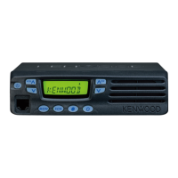
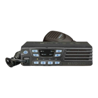
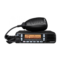
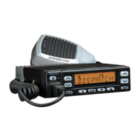
Description of front panel controls and indicators.
Description of the microphone and its connection.
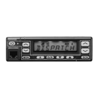
Explanation of display indicators and their meanings.
Explanation of display indicators and their meanings.
Description of rear panel connectors.
Details on programmable keys and functions.
Overview of operating modes (User, PC, Clone, Self Programming).
Procedures for accessing operational modes.
PC connection, interface cable, and software for programming.
Procedure for transferring programming data between transceivers.
Description and connection of the optional ignition sense cable.
Steps to connect the KCT-18 cable.
Steps for ignition key power control modification.
Explanation of receiver and transmitter frequency configurations.
Overview of the double conversion superheterodyne receiver.
Details on initial RF signal amplification and filtering.
Explanation of the first mixer and crystal filter stages.
Detailed pinout and function description for the TX-RX unit IC101.
Component list for the TK-8160 display unit.
Component list for the TK-8162 display unit.
Component list for the TX-RX unit.
Detailed parts list for the TK-8160 display unit.
Parts list for TK-8160 display unit variants.
Diagram showing the physical assembly of the transceiver unit.
Illustration of the product packaging and included accessories.
List of necessary test equipment and their specifications for alignment.
Description and pinout of the microphone test cable.
Pinout and function details for the CN2 connector.
Pinout and function details for the CN3 connector.
Assignment of functions to ports for accessories and modes.
Component layout on display unit's component side.
Component layout on display unit's foil side.
Component layout on TK-8162 display unit's component side.
Component layout on TK-8162 display unit's foil side.
Component layout on TX-RX unit's component side.
Schematic diagram for the TX-RX unit.
Block diagram of the TK-8160 display unit.
Block diagram of the TK-8162 display unit.
Block diagram of the TX-RX unit.
RF and AF level diagram for the receiver.
RF and AF level diagram for the transmitter.
General specifications including frequency range and operating conditions.
Receiver sensitivity and performance specifications.
Transmitter output power and modulation specifications.
| Frequency Range | 136-174 MHz |
|---|---|
| Channel Capacity | 128 |
| Channel Spacing | 12.5/25 kHz |
| Operating Temperature | -30°C to +60°C |
| Modulation | 16K0F3E |