Do you have a question about the Kenwood TK-8160 and is the answer not in the manual?
Manual purpose, parts ordering, and safety precautions.
Unpacking, pre-installation checks, and installation planning.
Notes on servicing and system setup procedures.
Flowchart for setting up transceiver options and accessories.
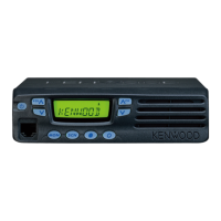
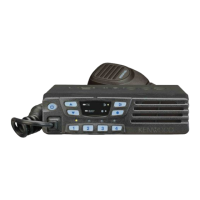
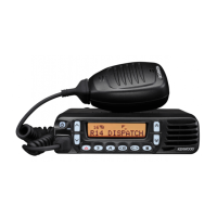
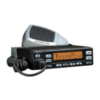
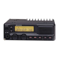
Overview of front panel controls, microphone, and their functions.
Explanation of icons and symbols shown on the TK-8160 display.
Explanation of icons and symbols shown on the TK-8162 display.
Diagram and description of rear panel connectors.
List of functions assignable to keys.
Overview of different transceiver operating modes.
Step-by-step guide to access various modes.
Procedures for programming via PC interface.
Method for transferring data between transceivers.
Procedure for setting a password to activate clone mode.
Guide for TK-8160 self-programming and password setup.
Flowchart and details for selecting items in self-programming.
Flowcharts for configuring individual settings.
Steps for installing the KCT-39 connection cable.
Connecting and modifying for ignition sense function.
Instructions for removing the transceiver panel and cabinet.
Explanation of receiver and transmitter frequency configurations.
Description of receiver stages like RF amplifier and mixer.
Explanation of the first IF stage and filtering.
Mechanism for selecting wide or narrow filters.
Path of the audio signal from detection to output.
How the squelch detection and control functions.
Explanation of PLL circuit and VCO for frequency generation.
Circuit operation for detecting PLL unlock during transmission.
General transmitter function, power amplification, and APC.
CPU operations for controlling various transceiver functions.
Description of the EEPROM for storing adjustment data.
How the CPU controls the LCD and LEDs.
How various data types are encoded for transmission.
How various data types are decoded upon reception.
Details of power supply management and protection circuits.
Detailed pin assignments and functions for the main microprocessor.
List of components on the TK-8160 display unit board.
List of components on the TK-8162 display unit board.
List of components on the TX-RX unit board.
Comprehensive list of parts for the TK-8160 display unit.
Comprehensive list of parts for the TK-8162 display unit.
Comprehensive list of parts for the TX-RX unit.
Visual guide showing how the transceiver is assembled.
Steps for packing the transceiver for shipment.
List of necessary equipment for alignment procedures.
Details on required cables for microphone input and tuning.
Diagrams showing where adjustments are made on the unit.
Important notes regarding EEPROM data and IC281 mounting.
Fuse installation and test frequency/signaling configurations.
Frequencies used for reference level adjustments.
Alignment procedures for specific PCB sections like VCO and IF coil.
Procedure for checking receiver sensitivity.
Procedures for adjusting squelch levels and RSSI.
Alignments for transmitter frequency and power output.
Adjustments for power, DQT, MAX balance, MIC sensitivity, and deviations.
Pin assignments for CN2 and CN3 connectors.
Details on function port assignments for various modules.
Component layout diagram for the display unit (component side).
Component layout diagram for the display unit (foil side).
Continued component layout for the display unit (component side).
Continued component layout for the display unit (foil side).
Component layout for TK-8160 display unit (component side).
Component layout for TK-8160 display unit (foil side).
Component layout for TK-8162 display unit (component side).
Component layout for TK-8162 display unit (foil side).
Component layout for the TX-RX unit (component side).
Continued component layout for the TX-RX unit (component side).
Continued component layout for the TX-RX unit (component side).
Continued component layout for the TX-RX unit (component side).
Continued component layout for the TX-RX unit (component side).
Component layout for the TX-RX unit (foil side).
Continued component layout for the TX-RX unit (foil side).
Continued component layout for the TX-RX unit (foil side).
Detailed circuit diagrams for the TX-RX unit.
Detailed circuit diagrams for the display unit.
Block diagrams for TK-8160 and TK-8162 display units.
Block diagram illustrating the TX-RX unit functional blocks.
RF and AF level measurements for the receiver section.
RF and AF level measurements for the transmitter section.
Continued RF and AF level measurements for the receiver.
Continued RF and AF level measurements for the transmitter.
General parameters like frequency range, channels, voltage, and dimensions.
Receiver performance metrics like sensitivity and selectivity.
Transmitter performance metrics like RF output power and modulation.
| operating voltage | 13.6 V DC ± 15% |
|---|---|
| current drain on standby | Less than 0.4 A |
| current drain on receive | Less than 1.0 A |
| current drain on transmit | Less than 8.0 A |
| operating temperature range | –30°C to +60°C |
|---|---|
| frequency range K | 450 to 490 MHz |
| frequency range M | 440 to 480 MHz |
| sensitivity 12dB SINAD wide | 0.28 µV |
|---|---|
| sensitivity 12dB SINAD narrow | 0.35 µV |
| selectivity wide | 75 dB |
| selectivity narrow | 65 dB |
| intermodulation wide | 70 dB |
| intermodulation narrow | 60 dB |
| spurious response | 75 dB |
| audio power output | 4.0 W |
| frequency stability | ± 2.5 ppm |
| RF power output high | 25 W |
|---|---|
| RF power output low | 5 W |
| spurious and harmonics | 70 dB |
| modulation wide | 16K0F3E |
| modulation narrow | 11K0F3E |
| FM noise wide | 45 dB |
| FM noise narrow | 40 dB |
| audio distortion | Less than 3% |
| frequency stability | ± 2.5 ppm |
| width | 6.30 inch (160 mm) |
|---|---|
| height | 1.70 inch (43 mm) |
| depth | 5.40 inch (137 mm) |
| weight | 2.60 lbs (1.18 kg) |