Do you have a question about the Kenwood TK-890/(B) and is the answer not in the manual?
How to order replacement parts, including part numbers.
Safety precautions for operating and servicing the equipment.
Information on FCC licensing and technician requirements.
Recommendation to check radio operation before installation.
Steps for planning radio and antenna mounting in a vehicle.
Guidance on antenna system and radio location for control stations.
Configuration option 1: Direct panel installation.
Configuration option 2: Single remote control.
Configuration option 3: Dual remote control.
Configuration option 4: Two radios, one controller.
Configuration option 5: Two radios, two controllers.
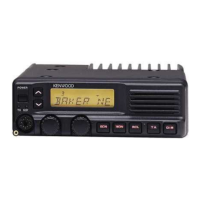
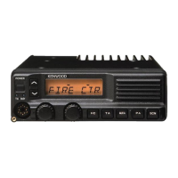
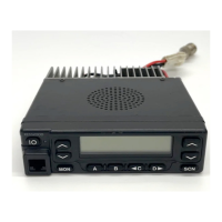
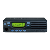
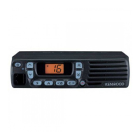
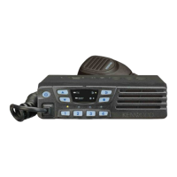
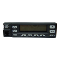
Description of controls and indicators on the radio panels.
Procedure to adjust the squelch level using front panel controls.
Amplifies microphone audio for PA speaker output.
Prevents interference with stations using the same channel.
Instructions for modifying the KPG-43 cable for PC tuning.
Explains All Clone Mode and Group Clone Mode.
How to select signaling from the programmed QT/DQT list.
Switches accessory PF Output ports programmed with AUX functions.
How to temporarily delete channels from the scan sequence.
Opens squelch only when a proper 2Tone code is received.
Disables transmission after receiving a DBD Code.
Function to switch display between group/channel number and name.
Opens squelch only when a proper DTMF code is received.
How to mute the speaker audio of another control head (Dual Head only).
Accesses the last called channel in scan mode.
Procedure to add current channel or group to scan sequence.
Interrupts continuous transmission after a specified time.
Overview of the 13 PF Ports and their programming.
Functionality of the UP/DOWN knob, programmable via FPU.
How to switch audio output between internal and PA speakers.
Allows immediate selection of a pre-determined Home Channel.
Adjusts brightness of display, LEDs, and key backlights.
Procedure to delete current channel or group from scan sequence.
Unmutes audio based on QT/DQT and 2Tone/DTMF combination.
Functions of programmable keys (PF1-9) and specific function keys.
Function to change scan DELETE/ADD settings.
Overview of ON HOOK and OFF HOOK scan modes.
How to set Priority 1 and Priority 2 channels.
Functions related to MSK PTT ID, including side tone and fleet ID.
How to change channels using UP/DOWN keys or knob.
Uses the radio as a repeater (Dual Band configuration only).
Automatic power switch-off function based on ignition status.
How to change groups using UP/DOWN keys or knob.
Function to alert via vehicle horn for incoming calls.
Initiates an emergency call and transmits emergency data.
Settings for emergency mode, including tone, display, and call type.
Steps for preparing and connecting for PC programming.
How to activate the optional voice scrambler function.
Direct access to specific channels.
Methods for using and enabling the optional voice scrambler.
Use of the KCT-18 cable for ignition and timed power off functions.
Methods for using and enabling the optional voice scrambler.
Modifying audio output for higher volume via control head.
Connection of the optional ANI board via connector.
Information about speaker output from TK-890 and KCH-11.
Function and modification for the horn alert pin.
Details of functions for the 25-pin accessory terminal.
Procedure to remove the TX-RX unit from the radio.
Steps to remove the Final Unit from the radio.
Steps to remove the case and shield cover of the radio.
Procedure to remove the TX-RX unit from the radio.
Steps to remove the Final Unit from the radio.
Steps to remove the Control Unit from the radio.
Steps to disassemble the KCH-10 display unit.
Procedure to remove the accessory connector from the rear of the unit.
Steps to disassemble the KCH-11 display unit.
Procedure for adjusting transmit frequency using panel keys.
Procedure to adjust MCF gain for wideband.
Procedures for adjusting maximum deviation for wide and narrow bands.
Procedure to adjust QT deviation for wide and narrow bands.
Procedures for adjusting receiver sensitivity (low, center, high).
Flowchart for entering panel test mode.
Procedures for adjusting BPF bandwidth for different models and revisions.
Procedure to adjust MCF gain for narrow band.
Procedure to adjust microphone sensitivity.
Procedure to adjust DOT deviation for wide and narrow bands.
Procedure to adjust squelch tight point.
Procedure to check and adjust distortion values.
Procedure to adjust DQT balance for modulation waveform.
Procedure to adjust DTMF deviation for wide and narrow bands.
Procedure to adjust squelch open point.
Procedure to enter and use panel tune mode for radio adjustment.
Procedures for adjusting RF power for high and medium power models.
Procedure to adjust MSK deviation for wide and narrow bands.
Procedure to enter and use panel test mode for measurement.
Procedure for checking PLL lock voltage.
| Brand | Kenwood |
|---|---|
| Model | TK-890/(B) |
| Category | Transceiver |
| Language | English |