EasyManua.ls Logo

Kenwood TK-860G User Manual

Kenwood TK-860G
67 pages
To Next Page IconTo Next Page
Page #1 background imageLoading...
Page #1 background image
© 2000-1 PRINTED IN JAPAN
B51-8498-10
(
N
)
1268
UHF FM TRANSCEIVER
TK-860G/862G
SERVICE MANUAL
REVISED
Microphone
(T91-0597-15)
Cabinet (Upper)
(A01-2165-13)
Panel assy
(A62-0642-03)
Key top
(K29-5343-02)
Microphone
(T91-0597-15)
Cabinet (Upper)
(A01-2165-13)
Panel assy
(A62-0731-03)
Key top
(K29-5344-02)
TK-860G (K)
TK-862G (K)
Please use this manual in place of the service manual (preliminary version), B51-8498-00.
We have added the information on the circuit description, specifications, and K3 version specifications to the service
manual (preliminary version), B51-8498-00.

Other manuals for Kenwood TK-860G

Question and Answer IconNeed help?

Do you have a question about the Kenwood TK-860G and is the answer not in the manual?

Kenwood TK-860G Specifications

General IconGeneral
BrandKenwood
ModelTK-860G
CategoryTransceiver
LanguageEnglish

Summary

General Information and Installation Planning

Pre-Installation Checkout and Testing

Steps for checking radio operation before final installation and testing with accessories.

Installation Planning Considerations

Guidance on planning the physical installation, antenna, radio location, and DC power wiring.

Control Station Installation Planning

Specifics for setting up a control station, including antenna and radio location.

Operating Features Overview

Controls and Functions

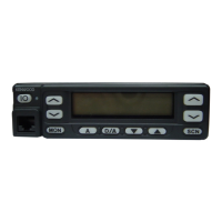
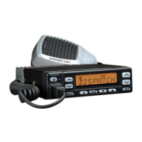
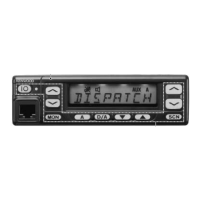
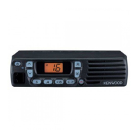
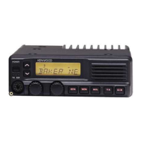
Overview of the transceiver's controls and their functions, including front panel and microphone.

Programmable Auxiliary Functions

Lists the keys and their potential programmable functions for enhanced operation.

Transceiver Controls and Indicators

Detailed breakdown of front panel controls, programmable keys, and indicators.

Programmable Keys Overview

Outlines how FPU enables programmable key functions for user customization.

Advanced Operating Features

Monitor and Operator Selectable Tone

Usage of Monitor function and Operator Selectable Tone (OST) for K market models.

TK-860G Scan Operating Modes

Explanation of Single group scan and Multiple group scan types.

Scan and Feature Details

Temporary Channel Management

Procedure for temporarily deleting or adding channels during scan operations.

Time-Out Timer and PTT ID

Configuration and operation of the time-out timer and PTT ID features.

Option Signalling and Feedback Tones

TOT Timer Functions

Details on TOT pre-alert, re-key time, and reset time functionalities.

Operator Selectable Tone (OST)

Functionality for selecting tone pairs on K market models for repeater access.

Option Signalling (DTMF/2-Tone)

Details on DTMF and 2-Tone decoders, AND/OR logic, Auto Reset, and Dead Beat Disable.

Operating Features and Realignment Modes

Transceiver Operating Modes

Overview of User mode, Panel test mode, PC mode, and Firmware programming mode.

Entering Operating Modes

Instructions on how to access each operational mode via panel keys.

Panel Test and Tuning Modes

Specifics for entering Panel Test Mode and Panel Tuning Mode.

Realignment Procedures

PC Mode for Programming

How to use PC Mode for programming via computer using KPG-46/56D.

Firmware Programming Mode

Procedure for upgrading the transceiver's firmware using a PC.

Advanced Programming and Cloning

Clone Mode Operation

How to transfer programming data between transceivers using a cloning cable.

Self Programming Mode (TK-860G)

How to enter and use the self programming mode for TK-860G.

Channel and Model Settings

Model Select Mode Procedures

Procedure for selecting the transceiver model within self programming mode.

Channel Setting Mode

How to configure individual channel settings using panel keys.

Channel Setting Mode Parameters

Option Signalling and ID Settings

Configuration for Option Signalling (DTMF/2-TONE) and ID settings.

PTT ID and Transmission ID Settings

Settings for PTT ID, Begin of TX ID, and End of TX ID.

Function Setting Mode Configuration

Key Assignments and Mode Settings

Foot Switch Function Assignments

Assigning functions like Emergency, Home Channel, and Scan to the foot switch.

Detailed Realignment Settings

Specific Feature Settings

Settings for Minimum Volume, Off Hook Enable, Horn Alert Disable, and Time Out Timer.

TOT Timers and Clear to Transpond

Configuration of TOT timers and Clear to Transpond function.

Delay and Dwell Time Settings

Configuration of Dropout Delay Time and Dwell Time.

Off Hook Scan Disable

Disabling the Off Hook Scan function.

DTMF and Reset Mode Settings

DTMF Timing and Dial ID Settings

Settings for Digit Time, Inter Digit Time, First Digit Time, Delay, and Dial ID.

DTMF Hold Time and Store/Send

Settings for DTMF Hold Time and the Store and Send function.

D Key Assignment and Group Codes

Assignments for D Key, DTMF Code Signalling, Inter mediate Code, and Group Code.

Realignment Flow Chart and Memory Reset

Overview of realignment flow chart and TK-860G memory reset modes.

Installation Procedures

KCT-19 Accessory Connection Cable

Details on the KCT-19 cable, its purpose, and installation.

Accessory Cable Connections

KCT-18 Ignition Sense Cable

Details on the KCT-18 cable and its ignition function.

Transceiver Modification and Speaker Connection

Modifying Transceiver for Ignition Control

Instructions to modify the transceiver for ignition key control of power/functions.

KAP-1 PA/HA Unit Installation

Instructions for installing the KAP-1 unit for Public Address/Horn Alert functions.

Speaker and Control Section Installation

Circuit Description Overview

Signal Processing Circuits

PLL Frequency Synthesizer Operation

Explains the PLL circuit's role in generating frequencies and its control.

Transmitter and Control Circuitry

Key Control and Memory Circuits

Signal Encoding and Decoding

Semiconductor Data and Components

Microprocessor IC502 Terminal Functions

Detailed pin assignments and functions for the microprocessor IC502.

Component Pin Assignments

Description of Components

Component Parts Lists

Detailed Parts Lists

Continued Parts Lists

Further Parts List Details

TX-RX Unit Parts List

Comprehensive Parts Lists

Detailed TX-RX Unit Parts

Final Parts List Sections

Adjustment Procedures

TK-860G Test Mode Operation

Instructions for entering and operating the TK-860G test mode.

Tuning Mode Settings

Alignment Test Equipment and Setup

Test Equipment for Alignment

Lists the necessary test equipment for transceiver alignment procedures.

Adjustment Locations and Notes

Common and Receiver Adjustments

Common Section Adjustment Procedures

Procedures for common adjustments, noting TK-862G requires FPU.

Squelch and Transmitter Adjustments

Transmitter Adjustments Overview

Procedures for adjusting transmitter parameters like Frequency and Power Output.

Transmitter Performance Adjustments

Frequency and Power Output Tuning

Procedures for tuning the transceiver's frequency and power output.

High and Low Power Adjustments

Procedures for adjusting high power and low power settings.

Transmitter Performance Tuning

Signal Deviation Adjustments

PC Board Layouts

PC Board Layouts (TK-862G and PLL/VCO)

TX-RX Unit PC Board Layouts

TX-RX Unit PC Board Diagrams

TX-RX Unit PC Board Layouts (B/2)

TX-RX Unit PC Board Layout Details

TX-RX Unit PC Board Views (B/2) Summary

Block Diagrams

Level Diagrams

Terminal Functions

Transceiver Specifications

Related product manuals