EasyManua.ls Logo

Kenwood TK-860HG User Manual

Kenwood TK-860HG
44 pages
To Next Page IconTo Next Page
Page #1 background imageLoading...
Page #1 background image
Document Copyrights
Copyright 2006 by Kenwood Corporation. All rights reserved.
No part of this manual may be reproduced, translated, distributed, or transmitted in any
form or by any means, electronic, mechanical, photocopying, recording, or otherwise, for
any purpose without the prior written permission of Kenwood.
Disclaimer
While every precaution has been taken in the preparation of this manual, Kenwood
assumes no responsibility for errors or omissions. Neither is any liability assumed for
damages resulting from the use of the information contained herein. Kenwood reserves
the right to make changes to any products herein at any time for improvement purposes.
Question and Answer IconNeed help?

Do you have a question about the Kenwood TK-860HG and is the answer not in the manual?

Kenwood TK-860HG Specifications

General IconGeneral
Frequency Range136-174 MHz
Channel Spacing12.5/25 kHz
Modulation16K0F3E / 11K0F3E
RF Output Power5W / 25W
Power Output25W
Channel Capacity128 channels

Summary

Document Copyrights

Operating Features

Emergency Mode Operation

How to activate and use the emergency mode feature.

Radio Password Security

Setting and using a password for transceiver access.

Realignment Procedures

Clone Mode Data Transfer

Transferring programmed data from master to slave radios.

Installation Guide

Ignition Sense and PA/HA Unit Installation

Connecting optional cables and units for enhanced functionality.

Installation Guide (Continued)

Transceiver Modification Options

Modifying the transceiver for horn alert and public address functions.

Parts List

Exploded View (TK-860HG)

Exploded View (TK-862HG)

Packing Instructions

Adjustment Procedures

Test Mode Operation and Calibration

Utilizing test mode for diagnostics and initial calibration.

Frequency and Signalling Calibration

Setting frequencies and signalling parameters for optimal performance.

Tuning Mode Parameters

Test Equipment and Cables

Adjustment Locations and Tools

Receiver Section Adjustments

Transmitter Section Adjustments

Transmitter Adjustments: Modulation and Deviation

Transmitter Adjustments: Deviation and Tone Control

PC Board Views

Display Unit Component Layouts

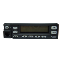
Component layout diagrams for the display unit.

PC Board Views (Continued)

PLL/VCO and Display Unit Views

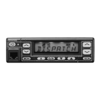
Component layout diagrams for PLL/VCO and display units.

TX-RX Unit (A/2) Component View

TX-RX Unit (A/2) Foil Side View

TX-RX Unit (B/2) Component Side View

TX-RX Unit (B/2) Foil Side View

Schematic Diagram

Block Diagram

Level Diagram

Terminal Function Reference

Technical Specifications

Related product manuals