Do you have a question about the Kenwood TK-880H and is the answer not in the manual?
Overview of the service manual's scope and intended audience.
Guidance on how to order replacement parts or equipment information.
Essential safety precautions for handling and operating the equipment.
Steps and checks before installing the radio, including unpacking and licensing.
Planning considerations for control station setup, including antenna and radio placement.
Explanation of the transceiver's operation in trunking and conventional modes.
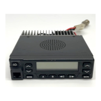
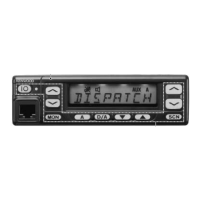
Overview of front panel controls and their functions, including LEDs.
Details the functions of individual push-button keys on the front panel.
Lists functions that can be assigned to programmable keys via FPU.
Details various functions assignable to keys, such as Auto TEL, AUX, DTMF, Emergency, etc.
Explains the meaning of various icons and LEDs on the front panel display.
Describes system scan and list type scan operations in trunking format.
Details system lockout, fixed lockout, user selectable lockout, and system/group revert options.
Explains scan massage wait, group scan, and conventional system scan types.
Describes single group scan and multiple group scan in conventional mode.
Details system lockout, fixed lockout, user selectable lockout, and system/group revert options.
Explains how to end a scan and temporarily add/delete channels.
Describes the function and programming of the Time-out Timer.
Explains the sub LCD display and the selective call alert LED function.
Details PTT ID, radio password entry, and off hook decode functions.
Explains the timed power off function and horn alert setup for trunking and conventional modes.
Covers call indicator, free system ringback, system search, and transpond features.
Explains transmit inhibit for ID codes and the Auto TEL function for telephone interconnect.
Describes TOT pre-alert and TOT re-key time settings.
Details TOT reset time, Operator Selectable Tone (OST) functions, and OST backup.
Explains DTMF/2-Tone decoder for signalling, including AND/OR conditions.
Covers MSK decoder for signalling and the Alphanumeric Two-way Paging Function (FleetSync™™).
Details selective call types and Unit ID encode block for limiting manual dial IDs.
Explains sending/receiving status messages, emergency status, and response settings.
Covers manual dial entry, FleetSync™™ baud rate, and message mode timer.
Describes GPS report modes, intervals, time marks, and sending GPS data.
Explains parameters for data transmission, including GTC count, retries, and wait times.
Details ACK delay time, TX delay time, and data TX modulation delay time.
Lists and describes various audible tones for user feedback, including power-on, alert, and key press tones.
Describes different operating modes like User, Panel test, PC, Firmware, Clone, and Self programming.
Instructions on how to enter each of the operating modes.
Details the procedures for entering Panel Test Mode and Panel Tuning Mode.
Explains how to use the PC Mode for programming via interface cable and software.
Details the procedure for upgrading the transceiver's firmware.
Provides notes on firmware programming and explains key functions within the mode.
Describes how to transfer programming data between radios using Clone Mode.
Explains how to enter and use Self Programming Mode for frequency and signalling settings.
Details how to configure individual channel settings using panel keys.
Describes how to set up various key functions and operational parameters.
Explains how to reset settings to default or clear all programmed data.
Details the KCT-19 cable and its installation procedure.
Lists the functions of each pin on the KCT-19 accessory connector.
Explains data equipment connections and required jumper settings.
Details the function of each terminal on the accessory connector.
Describes terminal assignments for optional boards and differences between schematic and PC board terminals.
Explains how to modify the transceiver to control power or horn alert via the ignition key.
Details the KCT-18 optional cable for ignition function and its connection.
Explains the KCT-29 cable for connecting GPS receivers/controllers and its installation.
Describes the KCT-31 RS-232C interface cable for LMR mobile radios.
Details KCT-31 installation and necessary modifications for COM2 port usage.
Describes the installation of the PA/HA Unit (KAP-1) for horn alert and public address functions.
Instructions for mounting the control panel in an upside-down orientation.
Details the installation of external speakers KES-3 and KES-4.
Explains the frequency configuration and double-conversion system of the TX-RX unit.
Provides an overview of the receiver system, including filters and amplifier stages.
Describes the circuit that switches between wide and narrow ceramic filters.
Details the audio processing and output path for AF signals.
Explains how the squelch circuit operates and is controlled by the CPU.
Overview of the transmitter system, including FM modulation and varicap diode usage.
Describes the Voltage Controlled Oscillator (VCO) and Phase-Locked Loop (PLL) synthesizer circuits.
Explains the circuit that controls transmission based on PLL lock status.
Details the stages involved in amplifying the transmit output signal.
Describes the Automatic Power Control circuit for stabilizing transmission output.
Outlines the tasks performed by the CPU for controlling various transceiver functions.
Explains the flash ROM and EEPROM used for storing firmware, data, and settings.
Describes how the CPU controls the shift register and display LEDs.
Explains the key matrix interface used for front panel button input.
Details the encoding process for QT, DQT, LTR, DTMF, and MSK signals.
Explains the function and operation of the Digital-to-Analog converter.
Describes the circuit responsible for controlling the horn alert function.
Explains the signal flow for the Public Address (PA) function when using the KAP-1 unit.
Details the power supply circuit, including over-voltage protection and timed power off function.
Lists pin functions for the microprocessor IC511 on the TX-RX Unit (B/2).
Lists pin functions for shift registers IC508 (B/2) and IC7/IC8 (A/2).
Lists and describes components on the TX-RX Unit (A/2), including ICs, Qs, and Diodes.
Lists and describes components on the TX-RX Unit (B/2) and the VCO Unit.
Explains how to identify capacitor types, values, and temperature coefficients.
Explains how to identify resistor types, values, and wattage ratings.
Lists parts for the TX-RX Unit (A/2), including cabinets, cables, and electronic components.
Lists chip capacitors C133 through C316 for the TX-RX Unit (A/2).
Lists chip capacitors C317 through C567 for the TX-RX Unit (A/2).
Lists chip capacitors C568 through C728 for the TX-RX Unit (A/2).
Lists inductors (L) and ferrite chips for the TX-RX Unit (A/2).
Lists resistors R233 through R548 for the TX-RX Unit (A/2).
Lists resistors R549 through R682 for the TX-RX Unit (A/2).
Lists diodes and varistors D503 through D520 for the TX-RX Unit (A/2).
Lists ICs and transistors for the TX-RX Unit (A/2).
Lists components for the VCO Unit (X58-4550-XX).
Lists capacitors and transistors for the VCO Unit.
Exploded view diagram showing assembly of the TX-RX Unit (A/2).
Exploded view diagram showing assembly of the TX-RX Unit (B/2).
Diagram showing the standard items included in the transceiver's packing.
Explains how to enter and use Test Mode for adjustments.
Provides tables for frequency and signalling values requiring adjustment.
Outlines necessary test equipment and procedures before transceiver tuning.
Details how to navigate and perform adjustments within Tuning Mode using panel keys.
Lists essential test equipment and their major specifications for alignment.
Shows diagrams for connecting tuning and test cables, including MIC connector pinout.
Identifies key adjustment locations and points on the transceiver PCBs.
Details the procedure for adjusting PLL lock voltage in test mode.
Covers adjustments for Discriminator, Sensitivity, Squelch, and QT.
Details adjustments for transmitter frequency, power output, and power checks.
Covers adjustments for modulation, maximum deviation, and MIC sensitivity.
Details adjustments for Fine LTR, DTMF, MSK, and TONE deviation.
Shows component layout for the PLL/VCO Unit on both sides.
Shows component layout for the TX-RX Unit (A/2) on both sides.
Continues showing component layout for the TX-RX Unit (A/2).
Shows component layout for the TX-RX Unit (B/2) on both sides.
Continues showing component layout for the TX-RX Unit (B/2).
Continues showing component layout for the TX-RX Unit (B/2).
Continues showing component layout for the TX-RX Unit (B/2).
Illustrates signal levels throughout the receiver section.
Illustrates signal levels throughout the transmitter section.
Lists pin functions for connectors CN7, CN502, and CN101.
Lists pin functions for connectors CN501 and J501.
Lists general specifications for the transceiver, including frequency range and power.
Details receiver performance specifications according to EIA standards.
Details transmitter performance specifications according to EIA standards.
| Brand | Kenwood |
|---|---|
| Model | TK-880H |
| Category | Transceiver |
| Language | English |