This product uses Lead Free solder.
This product complies with the
RoHS
directive for the European market.
© 2009-9 PRINTED IN JA PAN
B51-8887-00
(
N
)
533
SERVICE MANUAL
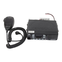
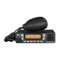
UHF FM TRANSCEIVER
CONNECTION CABLE
TK-8302/8302H
KCT-60
GENERAL .....................................................2
SYSTEM SET-UP .........................................4
REALIGNMENT ...........................................4
INSTALLATION ............................................6
DISASSEMBLY FOR REPAIR ......................8
CIRCUIT DESCRIPTION ............................10
SEMICONDUCTOR DATA .........................15
COMPONENTS DESCRIPTION .................16
PARTS LIST ...............................................17
EXPLODED VIEW ......................................26
PACKING ....................................................27
ADJUSTMENT ..........................................28
TERMINAL FUNCTION .............................34
PC BOARD
DISPLAY UNIT (X54-3670-20) ...............36
TX-RX UNIT (X57-7680-XX) ..................38
SCHEMATIC DIAGRAM ............................42
BLOCK DIAGRAM .....................................48
LEVEL DIAGRAM ......................................50
OPTIONAL ACCESSORIES
KCT-60 (CONNECTION CABLE) ............51
SPECIFICATIONS ...................BACK COVER
CONTENTS
Panel assy
(A62-1171-03)
Badge
(B43-1629-04)
Key top
(K29-9448-01)
Modular jack
(E58-0535-05)