EasyManua.ls Logo

Kenwood TM-V7A - User Manual

Kenwood TM-V7A
100 pages
Print Icon
To Next Page IconTo Next Page
Loading...
INSTRUCTION MANUAL
KENWOOD CORPORATION
TM-V7E
© B62-0678-20 (K,E,M)
09 08 07 06 05 04 03 02
TM-V7A
144/440 MHz FM DUAL BANDER
144/430 MHz FM DUAL BANDER
TM-V7A
144/430 MHz FM DUAL BANDER

Table of Contents

Other manuals for Kenwood TM-V7A

Questions and Answers

  • C
    Casey NobleAug 13, 2025
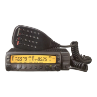
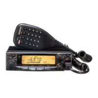
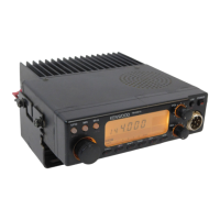
    Why won't my Kenwood Transceiver power on?
    • M
      markhallAug 13, 2025
      Your Kenwood Transceiver might not be powering on due to several reasons: * The power cable might be connected backwards. Ensure the red cable is connected to (+) and the black cable to (–). * A fuse in the power cable may be open. Identify the cause of the blown fuse and replace it with a new fuse of the same rating. * The front panel might not be securely connected to the main unit. Detach and reattach the front panel, ensuring it locks securely. * The connectorized cable may not be correctly connected. Ensure that the connectorized cable is correctly connected.
  • B
    Bobby RitterAug 17, 2025
    What to do if most buttons/keys and the Tuning control do not function on Kenwood Transceiver?
    • M
      michelle52Aug 18, 2025
      If most buttons/keys and the Tuning control are not working on your Kenwood Transceiver, it might be because one of the Lock functions is enabled. Try unlocking all Lock functions. Another potential cause is that the front panel is not securely connected to the main unit. Try separating the front panel from the main unit using the release switch on the rear of the front panel, then lock the front panel securely to the main unit using the same switch.
  • M
    Maria HamiltonAug 21, 2025
    What to do if I cannot transmit with my Kenwood Transceiver?
    • M
      Michael FergusonAug 21, 2025
      If you cannot transmit even when pressing the Mic [PTT] on your Kenwood Transceiver, ensure that the microphone plug is fully inserted into the front panel connector until the locking tab clicks. Also, check if you have inadvertently selected a transmit offset that places the transmit frequency outside the allowable range. To correct this, press [F], [SHIFT] repeatedly until neither '+' nor '–' is visible.
  • J
    Jean JonesAug 25, 2025
    What to do if my Kenwood Transceiver display is too dim?
    • P
      Peggy KimAug 26, 2025
      If the display on your Kenwood Transceiver is too dim, even at a high dimmer level, the supply voltage may be too low. The required supply voltage is 13.8 V DC ± 15% (11.7 V to 15.8 V DC). If the input voltage is outside of this range, recharge your battery, adjust your regulated power supply, and/or check all power cable connections.
  • A
    Arthur HarrisAug 29, 2025
    What causes strange functions or displays on Kenwood Transceiver?
    • C
      Carolyn ReedAug 29, 2025
      If your Kenwood Transceiver is displaying information strangely or functioning in an unexpected way, it could be due to soiled electrical contacts on the front panel and main unit. Clean the electrical contacts on both the front panel and the main unit using a clean damp cloth.
  • S
    Stephen DavisSep 1, 2025
    What to do if memory channels cannot be selected on Kenwood Transceiver?
    • M
      Mark NewmanSep 1, 2025
      If memory channels cannot be selected by turning the Tuning control or by pressing Mic [UP]/[DWN] when using Memory Recall on your Kenwood Transceiver, it could be due to a couple of reasons: * No data has been stored in any memory channels, or the stored data was erased by Full Reset. You should store data in some memory channels. * The Call channel was selected. Press [MR] to switch to Memory Recall.
  • T
    Travis McdanielSep 5, 2025
    Why can't I select frequency on my Kenwood Transceiver?
    • M
      Madeline LopezSep 5, 2025
      If you cannot select the frequency by turning the Tuning control or pressing Mic [UP]/[DWN] on your Kenwood Transceiver, it might be because Memory Recall or the Call channel was selected. To resolve this, press [VFO].
  • W
    wmillerSep 9, 2025
    Why am I having packet operation issues with my Kenwood Transceiver?
    • V
      Victoria ThompsonSep 9, 2025
      If you're experiencing no connects with other stations during packet operation with your Kenwood Transceiver, consider the following: * Your frequency may differ from the target station’s frequency. Adjust your frequency using the Tuning control. * The modulation level from the TNC may be incorrect. Adjust the TNC modulation level according to the TNC instruction manual. * There might be multi-path distortion. Try reorienting or relocating the antenna, as the strongest signal does not always provide the best packet operation. * The TX delay of your TNC may not be long enough. It is recommended to set the TX delay parameter on the TNC to 300 ms by using your computer.

Summary

MODELS COVERED BY THIS MANUAL

FEATURES

NOTICES TO THE USER

FCC Warnings and Information

Explains FCC compliance requirements and potential interference issues for digital devices.

PRECAUTIONS

Safety and Operational Precautions

Lists critical safety measures to prevent fire, injury, and equipment damage during operation.

SUPPLIED ACCESSORIES

CONVENTIONS FOLLOWED IN THIS MANUAL

PREPARATION FOR MOBILE AND FIXED STATION OPERATION

MOBILE INSTALLATION

Guide to safely and conveniently installing the transceiver inside a vehicle for mobile operation.

DC POWER CABLE CONNECTION

Instructions for connecting the transceiver's DC power cable for both mobile and fixed station use.

Replacing Fuses

ANTENNA CONNECTION

ACCESSORY CONNECTIONS

External Speakers and Microphone

Details on connecting external speakers (8 ohm) and the required microphone (600 ohm, 8-pin).

PACKET EQUIPMENT CONNECTIONS

YOUR FIRST QSO

GETTING ACQUAINTED

Basic Transceiver Modes Explained

Explains the functions and navigation for VFO, PM, Memory Recall, and Menu operating modes.

Band Selection and Display

BUTTON FUNCTION DISPLAY

FRONT PANEL Controls

Primary Control Buttons

Details the functions of key front panel buttons: CALL, VFO, MR, Tuning Control, and MHz Button.

Front Panel Function Buttons

Explains buttons like F, TONE, REV, LOW, SQL, VOL, and CONT SEL for advanced operations.

REAR PANEL Connectors

Antenna, Power, and Speaker Connectors

Describes the rear panel connections for antenna, 13.8V DC power input, and external speakers.

MICROPHONE Overview

Microphone Model Identification

Identifies the MC-53DM and MC-45 microphone models and their physical features.

Microphone Button Functions

Explains the operation and functions of all buttons on the MC-53DM and MC-45 microphones.

INDICATORS Explained

TRANSCEIVER GUIDE Function

OPERATING BASICS

Power, Volume, Squelch, and Band Selection

Step-by-step guide for essential operations: powering on/off, adjusting volume/squelch, and selecting bands.

SELECTING FREQUENCIES

Tuning Control and Microphone Buttons

Instructions on how to select operating frequencies using the Tuning control and microphone UP/DWN buttons.

TRANSMITTING

Selecting Output Power

Guidance on choosing the appropriate transmit power level for reliable communication and battery conservation.

MENU SET-UP

Understanding and Accessing the Menu

Explains the concept of menu-driven configuration and how to enter and navigate the menu system.

MENU CONFIGURATION

MEMORY CHANNELS

Simplex vs. Split Memory Channels

Differentiates between simplex and split memory channels and details the data storable in each.

VHF;UHF MEMORY CHANNEL RATIO

Storing Memory Data

Memory Channel Management

NAMING MEMORY CHANNELS

CALL CHANNEL

Recalling and Changing Call Channel

Procedures for recalling the Call channel and modifying its contents for simplex operation.

Split Call Channel and Memory Transfer

INITIALIZING MEMORY

Partial and Full Memory Resets

Guides on performing partial (VFO) and full (Memory) resets to restore factory default settings.

PROGRAMMABLE MEMORY (PM)

Programmable Settings Overview

Lists all settings that can be stored in PM channels, categorized by shared and band-specific parameters.

PROGRAMMABLE MEMORY APPLICATION EXAMPLES

PM Channel Data Management

PM Channel Storing and Reset

SCAN Functions Overview

VISUAL SCAN

Visual Scan Operation and Channel Selection

Details how to use Visual Scan to graphically monitor frequency activity and select the number of channels.

Using Visual Scan

SCAN RESUME METHODS

Selecting Scan Resume Method

Explains how to choose between Time-Operated and Carrier-Operated modes for scan resume behavior.

Scan Types

Locking Out Memory Channels

PROGRAM SCAN

Setting Scan Limits

Guides on defining up to three scan ranges (L1/U1, L2/U2, L3/U3) for Program Scan operations.

Advanced Scan Modes

Dual Band Scanning

CTCSS Functions

Using CTCSS and Tone ID

Explains CTCSS for selective communication and the Automatic Tone Frequency ID feature.

DTSS Functions

Storing DTSS Codes

Instructions on how to store DTSS codes for selective communication with specific stations.

Using DTSS

DTSS and Repeaters

PAGE Function

Page Code Memory and Communication Example

Details on using Page codes for station addressing, group calls, and includes a communication network example.

STORING PAGE CODES

Page Call and Receive Operations

LOCKING OUT PAGE CODES

Page Control Functions

DTMF FUNCTIONS

Making DTMF Calls and Autopatch

Covers making DTMF calls, using Autopatch services, and entering DTMF tones via the microphone keypad.

Mic Keypad Confirmation Tones

Explains how to enable feedback tones for DTMF keypad entries for confirmation.

DTMF Number Storage

DTMF Number Management

AUXILIARY FUNCTIONS

Time-Out Timer (TOT)

Function to restrict transmission time, useful for repeaters or battery conservation.

Automatic Power Off (APO)

Feature that automatically turns off the transceiver after a period of inactivity to save power.

Band Change and Interference Reduction

Dual Band RX and Display Control

Programmable VFO and Mode Switching

Frequency Step Size Adjustment

Button and Beep Configuration

LOCK Functions

Transceiver and All Lock Modes

Explains how to lock transceiver buttons and keys to prevent accidental setting changes.

S-METER SQUELCH

Squelch Hang Time Setting

Adjusts the time delay before squelch closes after a signal drops, used with S-meter Squelch.

Display Customization

Display Conditions Control

Display Dimmer

Adjusts the display illumination level for optimal visibility in various lighting conditions.

Auto Dimmer Change

Temporarily increases display brightness for 5 seconds upon button press or control turn.

Display Contrast and Reversal

CONFIGURING PROGRAM FUNCTION KEYS

KEYPAD DIRECT ENTRY

Frequency, Memory, and Tone Entry

Allows direct numerical input for frequencies, memory channels, and tone frequencies via microphone keypad.

CHANGING SPEAKER CONFIGURATIONS

MICROPHONE CONTROL

ACTIVATING MICROPHONE CONTROL

PACKET OPERATION

Data Band and Speed Settings

Covers activating the data TX/RX band and selecting data transfer rates (1200/9600 bps).

DATA CONNECTOR PIN FUNCTIONS

REPEATER FUNCTIONS (U.S.A.; CANADA ONLY)

Repeater Modes and TX Hold

Explains repeater modes (Cross-band, Locked-band) and the TX Hold function for repeater operations.

VS-3 VOICE SYNTHESIZER (OPTIONAL)

OPTIONAL ACCESSORIES

INSTALLING OPTIONS

VS-3 Unit and Detachable Panel Installation

Provides instructions for installing the VS-3 Voice Synthesizer and detachable front panel kits.

Installation Examples

MAINTENANCE

General Information and Service Notes

Covers factory alignment, service procedures, warranty, and notes for technical correspondence.

Cleaning Procedures

Instructions for safely cleaning the transceiver's controls and case using mild detergents and water.

TROUBLESHOOTING

SPECIFICATIONS

Kenwood TM-V7A Specifications

General Specifications IconGeneral Specifications
VHF frequency range144~148MHz
UHF frequency range438~450MHz (U.S.A/Canada)
Antenna impedance50Ω
Usable temperature range-20°C to +60°C (-4°F to +140°F)
Power supply13.8V DC ±15% (11.7~15.8V)
Grounding methodNegative-ground
Frequency stability±3ppm (-10°C to +50°C)
Dimensions (W x H x D)140 x 54.5 x 205.5 mm
Transmitter Specifications IconTransmitter Specifications
High power output50W (VHF) / 35W (UHF)
Mid power outputApprox. 10W
Low power outputApprox. 5W
Spurious emissions-60dB or less
Maximum frequency deviation±5kHz
Audio distortion3% or less (at 60% modulation)
Microphone impedance600Ω
Receiver Specifications IconReceiver Specifications
CircuitryDouble conversion
Intermediate frequency (1st / 2nd)38.85MHz / 450kHz and 45.05MHz / 455kHz
Sensitivity (VHF or UHF band)0.16μV or less (12dB SINAD)
Sensitivity (Sub VHF or UHF band)0.25μV or less
Selectivity (-6dB)12kHz or more
Selectivity (-60dB)28kHz or less
Squelch sensitivity0.1μV or less
Audio output2W or higher (8 ohms, 5% distortion)
Audio output impedance
Weight and Dimensions IconWeight and Dimensions
Weight1.2 kg (2.6 lb)
Dimensions (W x H x D)5.51" x 2.15" x 8.09"

Related product manuals