ADJUSTMENTS
TEST EQUIPMENT REQUIRED
1. Frequency Counter
Frequency range:
Up to 150 MHz or more
2.
SSG (Standard Signal Generator)
Capable of generating frequencies centering on 145
MHz, variable in amplitude, and also of frequency
modulation.
Output voltage: -10 dB-100 dB
AM
:
30% modulation at 1 kHz
FIVI: 7.5 kHz (1 kHz)
3. Oscilloscope
High-sensitivity oscilloscope, with external synch.
4. AF Vacuum-Tube Voltmeter
Frequency range: 50 Hz-10 kHz
lnput resistance: 1 megohm minimum
Voltage range:
F.S. =3 mV up to 30 volts
5. R F Vacuum-Tube Voltmeter
Frequency range: 150 MHz or more
6.
Vacuum-Tube Voltmeter
lnput impedance. 10 megohms or more
Voltage range: F.S.
=
0.1 up to 1000 volts,
AC and DC.
7. Power Meter
Power range:
F.S.
=
50W, 20W, 3W at 150
MHz or more
Input impedance of the meter should be 50 ohms.
8.
Linear Detector
Frequency range:
150 MHz or more
Frequency deviations:
10 kHz or more
The detector need not be used where high accuracy of
measurement is not required.
9.
AG (Audio Generator)
OLI tput: 300 Hz-5 kHz
Output voltage: 0.5 mV-1 V
10. AF Dummy Load
8
ohms and 3 watts approximately.
11. DC Regulated Power Supply
Voltage range: 9 V-16 V
Current range:
10A or more
,d
12. Sweep Generator
Center frequency: 145 WlHz
Frequency deviation: Maximum t5 kHz
Output voltage:
More than 0.1 V
Sweep rate:
At least 0.5 sec./cm
13. Center Meter
Input sensitivity: 50 pV or so
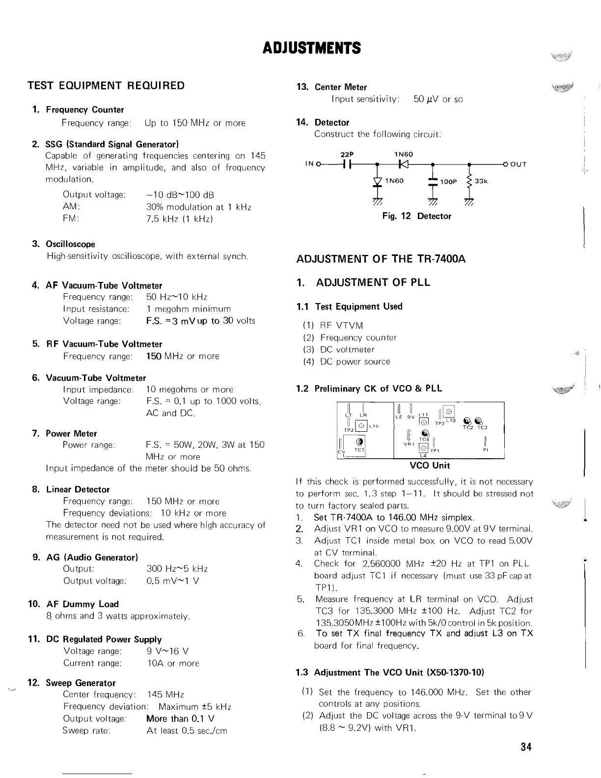
14. Detector
Construct the following circuit:
22P
lN-
OUT
I
Fig. 12 Detector
ADJUSTMENT
OF
THE TR-7400A
1.
ADJUSTMENT
OF
PLL
1.1 Test Equipment Used
(1) RF VTVlM
(2) Frequency counter
(3) DC voltmeter
(4) DC power source
1.2 Preliminary CK of VCO
&
PLL
TCZ
TC3
vco
unit
If this check is performed successfully, it is not necessary
to perform
sec. 1.3 step 1-1 1. It should be stressed not
to turn factory sealed parts.
1.
Set TR-7400A to 146.00 MHz simplex.
2.
Adjust VR1 on VCO to measure 9.00V at 9V terminal.
3. Adjust
TC1 inside metal box on VCO to read 5.00V
at CV terminal.
4. Check for 2.560000 MHz +20 Hz at TP1 on PLL
board adjust
TC1 if necessary (must use 33 pF cap at
TP1).
5. Measure frequency at LR terminal on VCO. Adjust
TC3 for 135.3000 MHz
flOO
Hz. Adjust TC2 for
135.3050MHz
f
100Hz with 5kIOcontrol in 5k position.
6.
To set TX final frequency TX and adjust L3 on TX
board for final frequency.
1.3 Adjustment The VCO Unit (X50-1370-10)
(1) Set the frequency to 146.000 MHz. Set the other
controls at any positions.
(2) Adjust the DC voltage across the 9-V terminal to 9 V
(8.8
-
9.2V) with VR1.