I
rounlesnoottng
(PLLJ
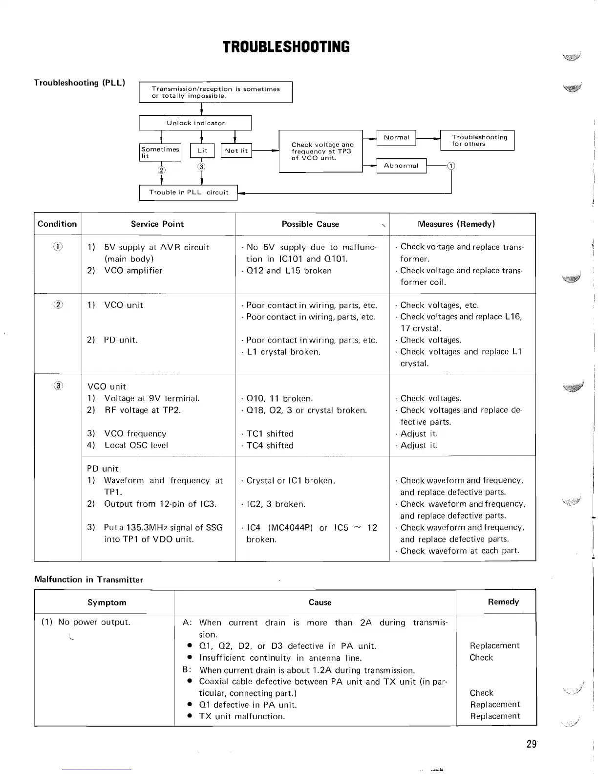
Transmission/reception is sometimes
or totally impossible.
+
Unlock indicator
Normal Troubleshooting
Check voltage and for others
-
frequency at TP3
of VCO unit.
Trouble in PLL circuit
Condition
(2)
(.$
Service Point
1)
5V supply at AVR circuit
(main body)
2) VCO ampiifier
1) VCO unit
2) PD unit.
--
VCO unit
1) Voltage at 9V terminal.
2) RF voltage at
TP2.
3) VCO frequency
4) Local OSC level
-
PD unit
1) Waveform and frequency at
TPI.
2)
Output from 12-pin of
IC3.
3)
Puta 135.3MHz signal of SSG
into
TPI of VDO unit.
Malfunction in Transmitter
Possible Cause
No 5V supply due to malfunc-
tion in
lClOl and 0101.
01 2 and L15 broken
Poor contact in wiring, parts, etc.
Poor contact in wiring, parts, etc.
Poor contact in wiring, parts, etc.
L1 crystal broken.
010,
I I
broken.
018, 02, 3 or crystal broken.
TC1 shifted
TC4 shifted
-
-
-
....
-..
.-
. Crystal or IC1 broken.
IC2, 3 broken.
.
IC4 (MC4044P) or IC5
-
12
broken.
Measures (Remedy)
. Checkvottage and replace trans-
former.
Check voltage and replace
trans-
former coil.
.
Check voltages, etc.
. Check voltages and replace L16,
17 crystal.
. Check voltayes.
Check voltages and replace
L1
crystal.
Check voltages.
Check voltages and replace
de-
fective parts.
Adjust it.
Adjust it.
-
Check waveform and frequency,
and replace defective parts.
Check waveform and frequency,
and replace defective parts.
. Check waveform andfrequency,
and replace defective parts.
Check waveform at each part.
Remedy
Replacement
Check
Check
Replacement
Replacement
Symptom
(1) No power output.
L
Cause
A: When current drain is more than
2A during transmis-
sion.
el,
02, D2, or D3 defective in PA unit.
Insufficient continuity in antenna line.
6:
When current drain is about 1.2A during transmission.
Coaxial cable defective between PA unit and TX unit (in par-
ticular, connecting part.)
01 defective in PA unit.
TX unit malfunction.