3
TS-2000/X
68.985MHz
75.825MHz
TX MIX
TX MIX
TX MIX
TX MIX
TX MIX
69.085MHz
10.695MHz
10.595MHz
75.925MHz
RX MIX RX MIX RX MIX
DET
TCAR
10.583MHz
455kHz
LO3
11.150MHz
LO1HF
75.955~
129.085MHz
LO2
58.390~
65.230MHz
RCAR
467kHz
41.795MHz
LO1TX
183.795~418.205MHz (K)
185.795~398.205MHz (E)
RX MIX RX MIX
41.895MHz
SUB
RX MIX
58.525MHz
LO1RX
183.895~
418.105MHz (K)
185.895~398.105MHz (E)
SLO2
58.070MHz
TX MIX TX MIX
135.395MHz
RX MIX RX MIX
135.495MHz
1.2GLO1
1104~
1165MHz
LO31
31.2MHz
Mixer
IF detector
÷2
SLO1
322.95~
465.04MHz (K)
371.475~409.050MHz (E)
HF/
50MHz
UHFVHF
1.2G
1.2GLO2
124.8MHz
DSP
MIC
input
AF
output
HF/50MHz LO1
When the HF and or 50MHz band is operating in the main
band, the HF REF VCO (Q427) generates 31.17 to 32.834
MHz. (See Table 1, frequency configuration.)
The output signal from the DDS (IC408) is input to pin 8
of the PLL IC (IC409) for HF REF, divided into 1/16 in IC409
to produce comparison frequency fø 2 of 487 to 513kHz.
The output signal from the VCO (Q427) goes to pin 6 of
PLL IC (IC409), is divided into 1/64 in IC409, and compared
with the signal with comparison frequency fø 2 by a phase
comparator. The frequency is locked and the HF REF signal
is output.
The output signal from the PLL IC (IC409) for HF REF is
fed to pin 8 of the PLL IC (IC414) for HF LO1 as a reference
frequency, and divided to produce comparison frequency
fø 1 of 975 to 1358kHz.
The HF LO1 VCO (Q459, Q460, Q464) generates 75.955
to 129.185MHz. The output from this VCO goes to pin 6 of
IC414, is divided into 1/N 1 in IC414, compared with the sig-
nal with comparison frequency fø 1 by a phase comparator.
The frequency is locked and the HF LO1 output frequency is
generated.
The DDS (IC408) sweeps output frequency (7.792 to
8.209MHz) in 10Hz steps by equation f
DDS STEP (Hz) =
(10*R 1)/(N 1*4) and in 1Hz steps by equation f
DDS STEP
(Hz) = (1*R 1)/(N 1*4), the HF LO1 covers the frequencies
of 75.955 to 129.085MHz in 10Hz or 1Hz steps.
One of three VCOs (Q459, Q460, Q464) is selected by
the signal (HF VCO1,HF VCO2,HF VCO3) from the serial-par-
allel IC (IC404).
The output from the VCOs (Q459, Q460, Q464) passes
through a buffer amplifier (Q462), is amplified by Q476, and
passes through a low-pass filter. The impedance is con-
verted by an attenuator and the signal is output as HFLO1.
The cut-off frequency of the low-pass filter in the output
section is changed by turning Q474 ON/OFF with a VCO se-
lect signal (HF VCO1).
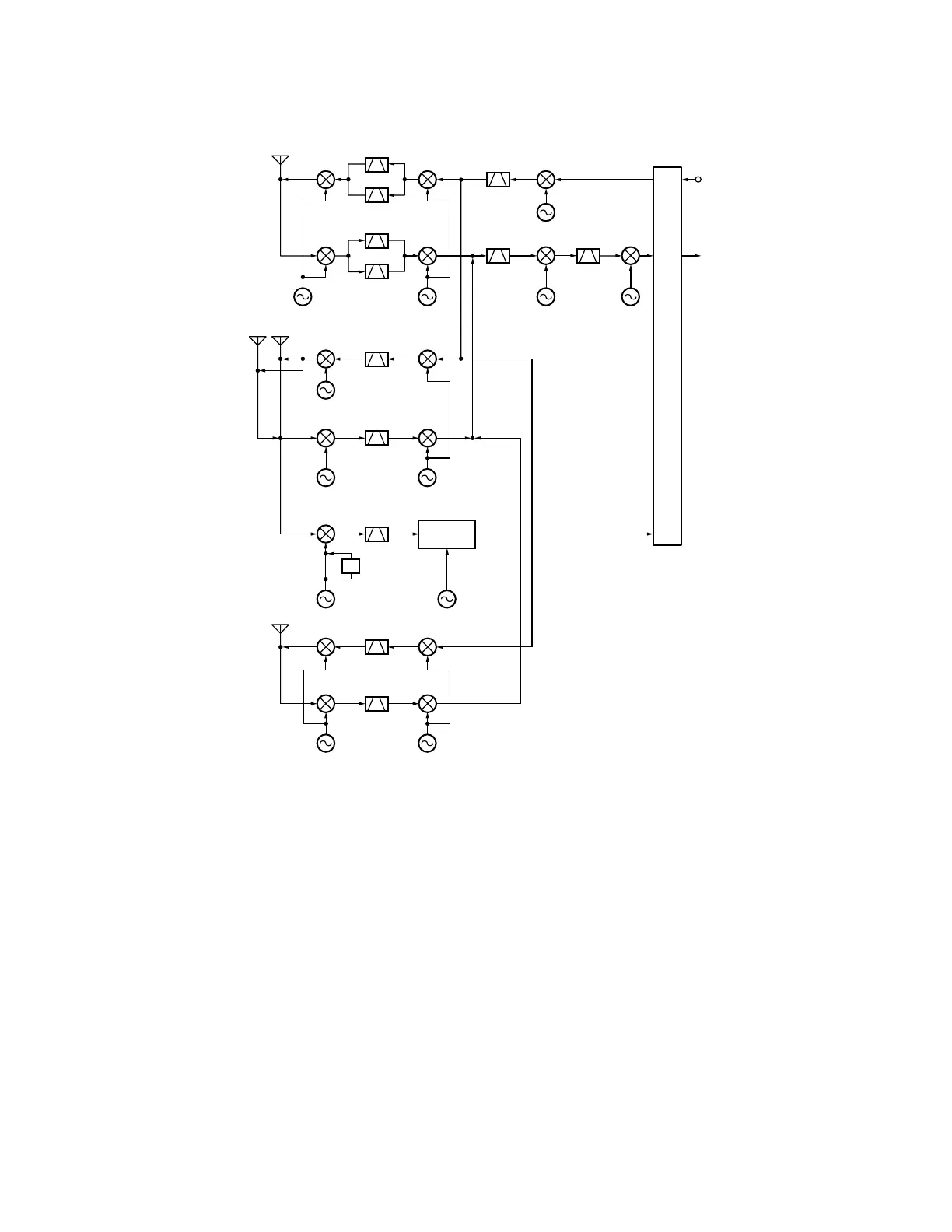
Fig. 1 Frequency configuration
CIRCUIT DESCRIPTION
 Loading...