EasyManua.ls Logo

Kenwood TS-480SAT Service Manual

Kenwood TS-480SAT
158 pages
To Next Page IconTo Next Page
Page #1 background imageLoading...
Page #1 background image
© 2003-11 PRINTED IN JAPAN
B51-8667-00
(
N
)
694
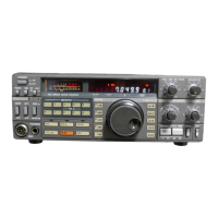
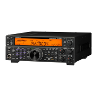
HF / 50MHz ALL MODE TRANSCEIVER
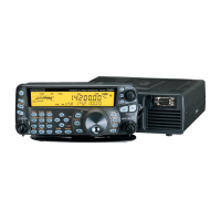
TS-480HX/480SAT
SERVICE MANUAL
DISASSEMBLY FOR REPAIR .................................. 2
CIRCUIT DESCRIPTION ........................................... 3
COMPONENTS DESCRIPTION ............................. 14
SEMICONDUCTOR DATA ..................................... 20
PARTS LIST ............................................................ 27
EXPLODED VIEW................................................... 50
PACKING ................................................................ 54
ADJUSTMENT ....................................................... 55
INTERCONNECTION DIAGRAM ........................... 76
PC BOARD / SCHEMATIC DIAGRAM
RF UNIT (X44-327X-XX) .................................... 78
FINAL UNIT (X45-365X-XX) (A/3)..................... 86
FINAL UNIT (X45-365X-XX) (B/3) ..................... 93
FINAL UNIT (X45-365X-XX) (C/3) ..................... 96
FINAL UNIT (X45-366X-XX) (A/3)..................... 98
FINAL UNIT (X45-366X-XX) (B/3) ................... 105
FINAL UNIT (X45-366X-XX) (C/3) ................... 108
DISPLAY UNIT (X54-3410-00) (A/3, B/3, C/3)
....... 110
TX-RX UNIT (X57-663X-XX) (A/2, B/2) .......... 116
SUB UNIT (X58-4900-XX)................................ 128
TERMINAL FUNCTION ........................................ 129
BLOCK DIAGRAM ................................................ 134
LEVEL DIAGRAM ................................................. 136
ACCESSORIES ..................................................... 140
SPECIFICATIONS ................................................. 141
Knob
(K29-9270-03)
Knob (Main dial)
(K21-1105-03)
Knob ring
(K29-9264-04)
Knob
(K29-9266-03)
Knob
(K29-9267-03)
Cabinet (Lower)
(A01-2190-02)
Knob
(K29-9265-03)
Knob
(K29-9267-03)
Panel assy
(A62-1076-03)
Key top
(K29-9263-02)
Stand
(J09-0409-03)
Microphone
(T91-0638-05)
Cabinet (Upper)
(A01-2189-02)
Panel
(A62-1079-01)
Foot
(J02-0441-05) x 4
CONTENTS

Other manuals for Kenwood TS-480SAT

Questions and Answers:

Kenwood TS-480SAT Specifications

General IconGeneral
Antenna Impedance50 ohms
Supply Voltage13.8 V DC ±15%
Current Drain (Receive)1.5 A
Antenna ConnectorSO-239
Operating Temperature-10°C to +50°C
ModesSSB, CW, AM, FM, FSK
Antenna TunerBuilt-in
Current Drain (Transmit)20.5 A
Power Output100 watts
RF Output Power100 watts

Summary

Disassembly for Repair

How to Remove the Torque Changeover Lever

Step-by-step instructions for removing the torque changeover lever from the unit.

How to Mount the Torque Changeover Lever

Instructions for correctly mounting the torque changeover lever onto the unit.

Circuit Description

Reference Signal Generator

Explanation of the reference signal generation circuit and its role in PLL frequency control.

LO1/LO2/CAR

Description of the local oscillators (LO1, LO2) and carrier generation circuits.

From detection to AF output

Explanation of the AF signal processing path from detection to audio output.

Transmitter Circuit

Overview of the transmitter circuit, including power output types and unit differences.

Components Description

RF Unit (X44-327X-XX)

Detailed description of components within the RF unit, including their functions and conditions.

Final Unit (X45-365X-XX) (A/3)

Detailed component list and function description for the Final Unit (A/3).

Semiconductor Data

Main Microcomputer : HD64F2338VFC25 (TX-RX Unit IC204)

Pin assignments, I/O functions, and specification details for the main microcomputer.

Parts List

RF UNIT (X44-327X-XX)

Comprehensive list of parts used in the RF unit, including part numbers and descriptions.

Final Unit (X45-365X-XX)

Comprehensive list of parts used in the Final Unit, including part numbers and descriptions.

Exploded View (Main Body Upper Side)

Packing

Adjustment

Required Test Equipment

List of essential test equipment required for performing adjustments on the transceiver.

Preparation

Initial settings for knobs and switches as per service manual requirements.

Updating the Firmware

Instructions and requirements for updating the transceiver firmware using a PC.

Interconnection Diagram

PC Board

RF UNIT (X44-327X-XX)

Component placement diagram for the RF unit's main circuit board.

TX-RX UNIT (X57-663X-XX)(A/2) 0-11 : KH 0-12 : KS 2-71 : EH 2-72 : ES

Component layout for the TX-RX unit, detailing connections and part locations.

100W FINAL UNIT (X45-365X-XX) (A/3) 0-11 : KS 2-71 : ES

Component placement diagram for the 100W Final Unit (A/3), showing the layout of components.

Block Diagram

Level Diagram (RX Section)

Level Diagram (TX Section)

Accessories

Specifications

General

General specifications including mode, memory channels, supply voltage, and operating environment.

Transmitter

Detailed transmitter specifications including frequency range, output power, and modulation characteristics.

Receiver

Detailed receiver specifications including circuit type, sensitivity, selectivity, and audio output.

Terminal Function

RF UNIT (X44-327)

Detailed pin functions and descriptions for the RF unit's connectors.

TX-RX UNIT (X57-663 A/2)

Terminal functions for the TX-RX unit, covering various input/output signals and control lines.

SUB UNIT (X58-490)

Terminal functions for the sub unit, detailing connections to other main units.

Related product manuals