SELENA Multifunctional LED Clock USER MANUAL V32D
KERA TECHNOLOGIES INC. 2013 www.ledclocks.com
23
To be able to control the Internal Buzzer operation during the Timer Alarm periods, enable the function Fn 17 (see
FUNCTION SETUP Procedure section).
To SILENCE THE INTERNAL BUZZER ONLY without affecting the RELAY 1 during a pending Alarm, press the MUTE key.
To DISABLE THE INTERNAL BUZZER PERMANENTLY , disable the function Fn 17.
To SILENCE THE BUZZER and DEACTIVATE the ALARM RELAY 1 during a pending Alarm, press the SET key and wait a
few seconds.
To DISABLE the MULTI-EVENT TIMER operation:
disable the Multi-Event Timer function Fn 48 (see FUNCTION SETUP Procedure section). All previously preset events data
will be retained in the memory unaffected.
For instructions on how to connect external loads to the Internal Alarm Relays contacts,
see the section: “INTERNAL CONTROL RELAY Wiring“.
INTERNAL CONTROL RELAY
( Optional Feature )
The internal control Relay 1 is enabled by enabling the function Fn 37.
The Relay 2 is enabled by specific applications.
The Presettable Stopwatch/Timer/Counter, Programmable Thermostat, Programmable Multi-Event Timer and Temperature
HIGH/LOW ALARM can activate ONE or TWO internal Control Relays that can be used to switch external loads up to
10Amp/240VAC. Both of the Internal Relays have SPDT contacts available, but may not be accessible to the user in some
models. For instance, in the Programmable Thermostat mode, only either the Normally Open or Normally Closed SPST
contacts are usually wired from both internal relays. Ask for the specific access to the relays contacts when ordering.
NOTE, that in the Stopwatch/Timer/Counter applications, if the function Fn 49 is enabled, the internal relay 1 will remain active
only for a 3 seconds period.
INTERNAL CONTROL RELAY Wiring
Make sure that all power is disconnected.
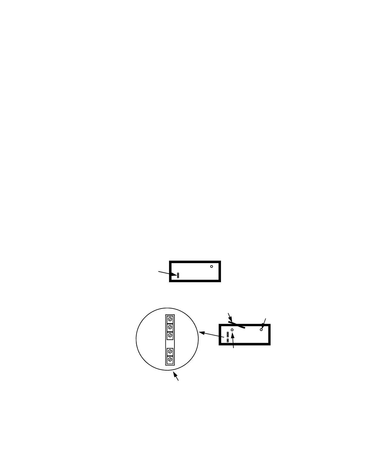
1. Locate the Relay Contacts screw terminal block on the back panel of the enclosure.
A) Internal Relay Only installed:
B) Internal SPDT Relay and Internal DC Power Source:
2. Attach the load wiring to the terminal and secure it with the terminal screws.
NOTE: The wiring should be of sufficient gauge to carry the load current and insulation should be appropriate for the
load voltage. Remember to provide adequate fuse protection.
Internal Relay
Contacts Terminal
RELAY
Relay Contacts and optional Internal DC Supply Terminals
Internal DC Source Fuse
( Value Depending upon the
model )
NO - C - NC + 12V -
RELAY
Int. Sup.
Power line Fuse
POWER CORD
(if installed)
NOTE:
Normally the internal DC
voltage is filtered but NOT
regulated and may vary from
appx. 11V to 16VDC.