SELENA Multifunctional LED Clock USER MANUAL V32D
KERA TECHNOLOGIES INC. 2013 www.ledclocks.com
46
CONTROL RELAY Operation in LOW/HIGH TEMPERATURE ALARM application
The Internal Relay can be controlled by the Low/High Temperature Alarm ONLY when the function Fn 37 is NOT ENABLED.
The Internal Control Relay operates in several different modes depending upon the setting of the function Fn 18 and Fn 16.
1. When Fn 18 is enabled, the Internal Relay will be switched OFF when the Temperature ALARM occurs and ON
when there is NO ALARM condition.
2. When Fn 18 is NOT ENABLED, the Internal Relay will ONLY be switched OFF in response to the HIGH
Temperature ALARM and ON when the Temperature is lower than the HIGH ALARM preset, even if it is lower
than the LOW ALARM preset.
When the RELAY LATCHING is enabled (by enabling the function Fn 16), once energized, it will remain ON even if the
temperature falls back within the NO-ALARM range. The relay may be reset manually by pressing the CLR key twice while
the temperature is NOT in the Alarm range.
NOTE, that the internal relay installed is usually SPDT type and therefore both the Normally Open and the Normally
Closed contacts are available at the terminal block.
VISUAL INDICATIONS
To change the display unit between Celsius and Fahrenheit, enable ( Celsius ) or disable ( Fahrenheit ) the function Fn 15.
A) The Display will show the INTERNAL probe temperature if the function Fn 0 is enabled.
B) The Display will show the EXTERNAL probe temperature if the function Fn 1 is enabled.
When both Fn 0 and Fn 1 are enabled, the digital display section will also show a short text designating which temperature
probe test is about to be displayed. This text contents may be selected using the functions Fn 94 and 95 as follows.
Fn 94 Fn 95 Displayed text
0FF OFF “In” and “Out”
0N OFF “Air” and “h2o”
0FF ON “Air” and “Pool”
0N ON “Pool” and “Out”
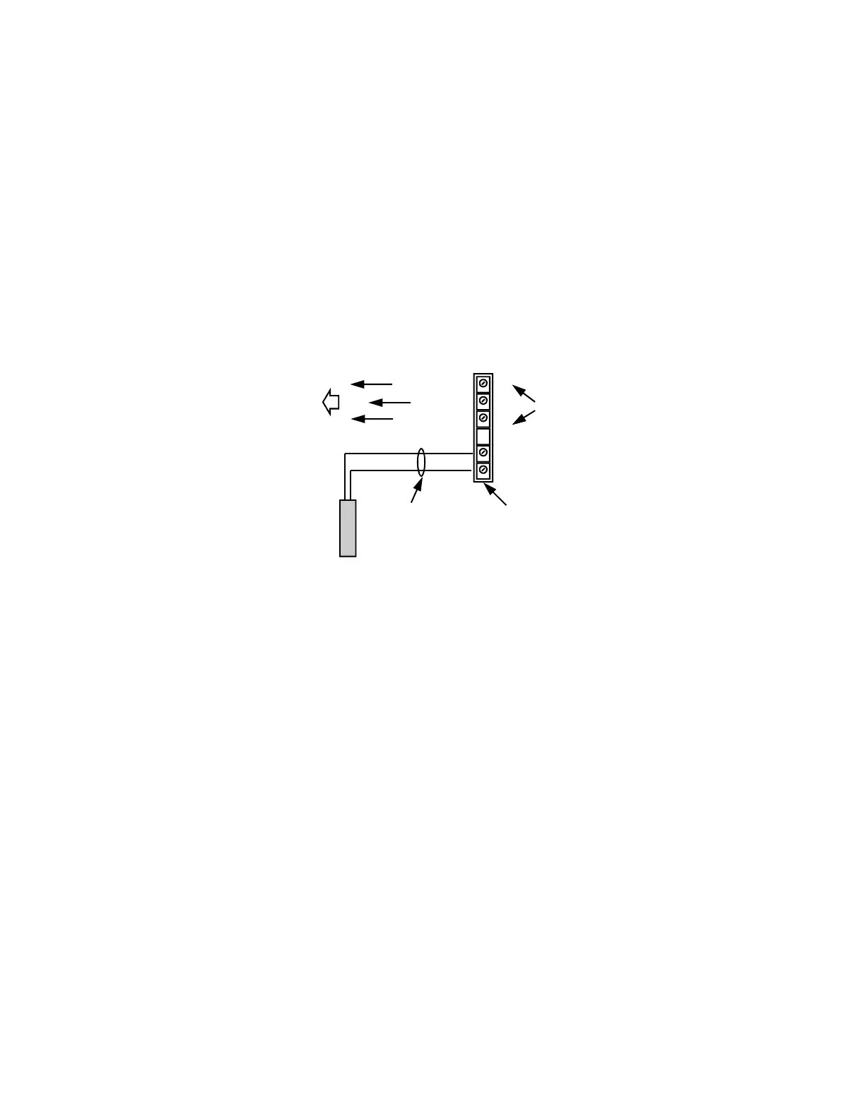
Note, that both probes may be connected to the external terminal block and may be wired up to 500 feet ( 150 m ) away from
the display, using any kind of a 2-conductor cable. Optionally, a model may be ordered with one probe installed in the wall of
the display enclosure.
Note, that either one or both temperatures may be enabled to be displayed in sequence alone or also with other display
modes enabled by any of the functions from Fn 2 to Fn 7.
When the temperature is set to alternate with any other display, it is possible to change the duration of displaying of each of
the screens. This persistence is controlled by enabling or disabling the functions Fn 40 and Fn 41 as required.
In clocks with the Electronic TEXT display, the temperature may be also displayed in that section and it may be made to
alternate between several different screens as well ( see Fn 75, 76, 77, 85).
Terminal block
on the back panel
Ctrl. Contacts
PROBE
TO THE HEATING SYSTEM
OR
TO THE AIR CONDITIONING SYSTEM
CONTROL INPUTS
External Temperature
PROBE
NORMALLY OPEN
NORMALLY CLOSED
Use any type
2-conductor cable to
extend the probe wiring
up to 500 ft ( 150m )
Wiring for ONLY Heating ( or ONLY Air-Conditioning ) system with one Internal SPDT Relay
and with one external probe.
COMMON
10 Amp. , 250V max.
CAUTION !
The relays contacts are not fused.
Provide appropriate fuse protection in
the external wiring !