PARADIGM – INSTALLATION/OPERATION MANUAL
Paradigm
14 Jun 10
4.0 OIL TANKS & PIPING
Tank installation must conform to local requirements.
Install according to the applicable code. Minimize number of connections in suction line and
make all connections as tight as possible. Use a pipe joint compound suitable for oil on all pipe
threads. To reduce possibility of air leaks, tighten stem packing gland nut on any valves
installed in the suction line. Also, be sure the oil filter is tight, as filter gaskets often shrink.
Check for kinks in the oil lines as well as for possible air pockets and for loose connections.
Two filters as shown in Figure – 3 are recommended. The filter before the burner must be a 10
Micron or better. Optional tank gauge protectors and outlet protectors are available at your
local Kerr dealer.
ONE PIPE SYSTEM Where the tank is above the burner and when the oil flows by gravity to
the oil pump, a single-stage fuel unit with a single oil line to the pump
may be used.
TWO PIPE SYSTEM When single line is unsuitable, use double line or see your Kerr dealer
for special oil line fittings.
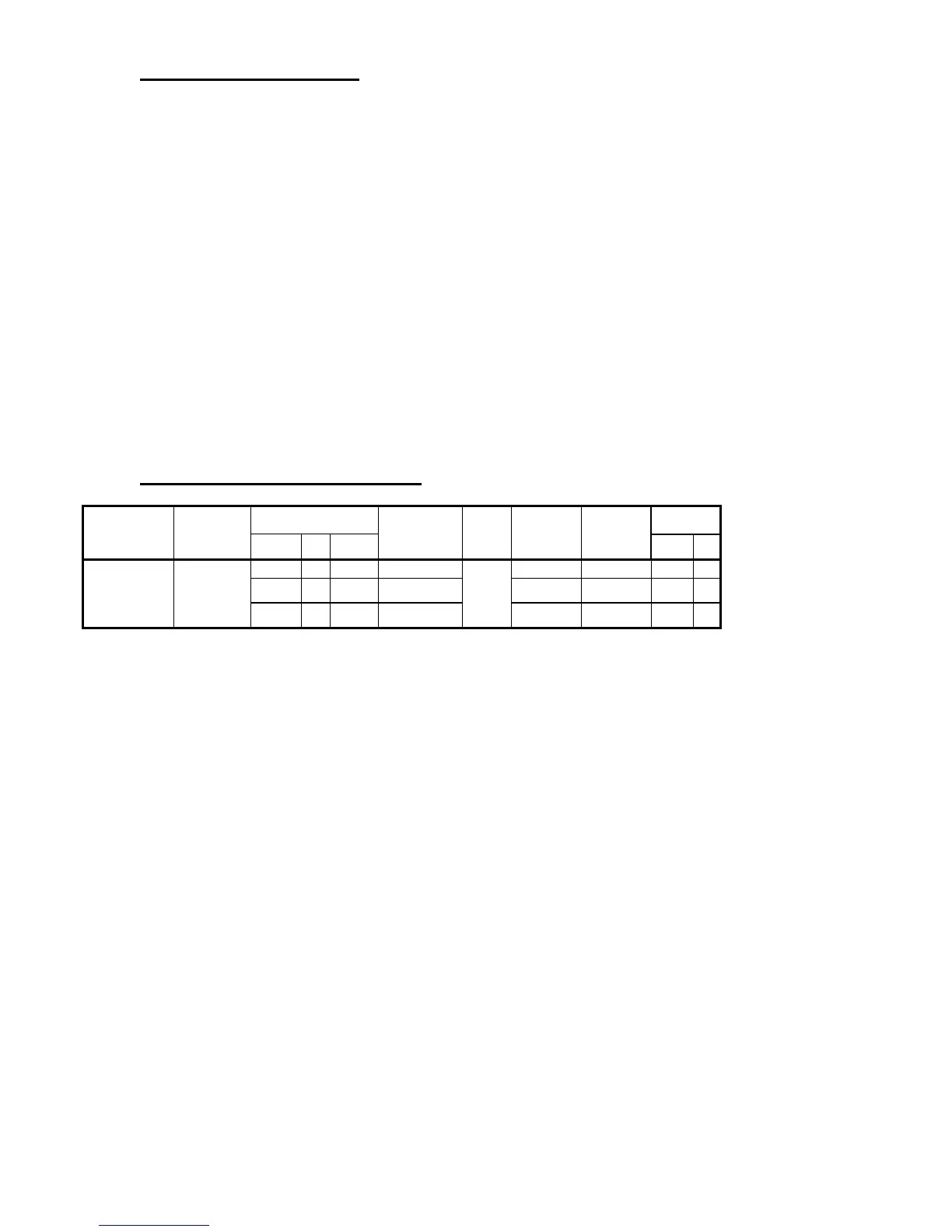
5.0 BURNER SPECIFICATIONS
Model Burner
Input
Nozzle
Pump
(psi)
Air Setting Turbulator
Output
The turbulator & air
settings found on this
page should be used
as a guide.
USGPH L/h Btu/h Btu/h kW
KPR-V1-0100-E4 Riello 40 BF3
0.49 1.85 68,600 0.40 60W
150
3.2 1.0 66,500 19
0.61 2.31 85,400 0.50 60W 4.0 1.5 83,600 24
0.73 2.76 102,200 0.60 60W 4.8 2.0 98,000 29
Use Delavan nozzles. Set flame to #0-1 smoke before CO
2
test. The information provided by
the manufacturer of this furnace supersedes any information provided by any other party
including the manufacturer of the burner.
 Loading...