PARADIGM – INSTALLATION/OPERATION MANUAL
Paradigm
6 Jun 10
ENSURE THAT ENOUGH ROOM IS LEFT TO REMOVE THE AIR FILTER IF REAR FILTER
DOOR LOCATION IS SELECTED.
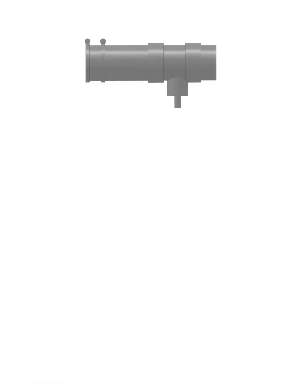
A second neoprene pipe coupling (Clamp-All) is supplied that can be inserted in the vent to
enable a section of the vent to be removed for furnace cleaning. It is better to have the second
neoprene pipe coupling inserted on a vertical rise to easily accommodate the removal of the
vent section.
Ensure that the vent slopes back to the furnace.
TERMINATION The IPEX System 636 PVC Concentric Vent Kit (termination), 196006 and
the Termination Vent Screen, 196051 is supplied with the furnace. The
parts of the termination, with the exception of the conical exterior end,
must be glued together after they are fitted for the wall installation. The
conical exterior end can be glued in place after the termination is installed
in the wall. The termination screen should be installed in the outside of the
termination as a friction fit. Removal of the screen may be necessary in
the future for cleaning purposes.
SIDEWALL VENT The sidewall vent must be installed in accordance with the appropriate
installation code.
CONDENSATE
The Paradigm Condensing Furnace comes with two hoses attached to the
DRAIN back left hand side.
The bottom clear plastic hose is to be connected to the vent tee. It allows
condensate from the vent tee to travel to the input side of the condensate
neutralizer. This hose has a furnace label “From Vent Tee to Condensate
Neutralizer”. The vent tee and the furnace collector drain connect to the
bottom of the neutralizer canister with a tee connection. The condensate
fills the neutralizer canister rising up and draining out the top.
The top plastic tube is the drain from the neutralizer, the decal next to the
port says “From Condensate Neutralizer to Drain”. This is the conditioned
condensate which should be drained to the waste water system.