EasyManua.ls Logo

Keter DARWIN 100G User Manual

Keter DARWIN 100G
16 pages
To Next Page IconTo Next Page
Page #1 background imageLoading...
Page #1 background image
MANUAL
Create amazing spaces
DARWIN 100G
5008904
USER MANUAL | MODE D’EMPLOI | MANUAL DEL USUARIO | GEBRAUCHSANLEITUNG |
GEBRUIKSHANDLEIDING | MANUALE PER L’UTENTE | MANUAL DO UTILIZADOR |
www.keter.com
US, Canada
Tel: +1877-638-7056, NACS@keter.com
Mon - Fri | 8am - 6pm ET / Lundi-Vendredi 8h -18h
Sat - Sun | 9am - 6pm ET / Samedi-Dimanche 9h-18h
UK
Tel: +44-121-506-0008, CSUK@keter.com
Mon - Fri | 8:30am - 5pm
For other European countries see the last page
Pour les autres pays d’Europe, voir la dernière page
Para otros países europeos vea la la última página
272Kg
600
Lb
75Kg
165
Lb
X2
Question and Answer IconNeed help?

Do you have a question about the Keter DARWIN 100G and is the answer not in the manual?

Keter DARWIN 100G Specifications

General IconGeneral
Product NameKeter DARWIN 100G
CategoryIndoor Furnishing
MaterialResin
ColorGray
Capacity100 gallons
Assembly RequiredYes
Floor IncludedYes

Summary

Product Identification and Specifications

Product Details

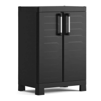
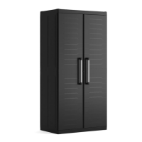
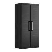
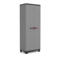
Manual title, product name, and capacity specifications for the Keter Darwin 100G.

Assembly Preparation

Component Identification

Lists all parts and hardware required for assembling the Keter Darwin 100G.

Pre-Assembly Safety Precautions

Essential safety guidelines and warnings to follow before starting the assembly process.

Assembly Instructions

Step 1-2: Initial Panel Assembly

Attaching the first side panels (DCP1) and base (DEF) to form the initial structure.

Step 3-4: Adding Side Panels

Securing additional side panels (DP1, DCP1) to build the storage box walls.

Step 5-6: Continuing Wall Assembly

Attaching more side panels (DP1, DCP1) to extend the box structure.

Step 7-8: Completing Side Walls

Finalizing the side wall construction with panels (DP1, DCP1).

Step 9-10: Rear Panel and Lid Attachment

Installing rear panels (DP1) and placing the lid (DE) onto the assembled box.

Step 11-12: Securing the Lid

Fastening the lid to the main box structure using screws (S25).

Step 13-14: Base Reinforcement

Adding screws (S25) and base connectors (DC, DCC) for structural integrity.

Step 15-16: Floor Support Installation

Attaching floor supports (DC, MG) and latches (SOP) using screws (S14).

Step 17-18: Lid Support and Hinges

Installing lid supports (WL1, DEH) and securing them with screws (S14).

Step 19-20: Lid Latch and Optional Locking

Attaching the second lid support (WL2) and noting the option for a lock.

Warranty Information

Limited 2-Year Warranty Details

Explains the terms, conditions, and exclusions of the 2-year limited warranty.

Care and Safety

Usage and Maintenance Guidelines

Provides essential care instructions and safety warnings for proper product use.

Contact and Support Information

Customer Service and Distributors

Contact details for customer service and a list of distributors worldwide.

Related product manuals