EasyManua.ls Logo

Key Automation CT102 24 - Introducing the Product; Description of the Control Unit; Description of the Connections; Models and Technical Characteristics

Key Automation CT102 24
16 pages
To Next Page IconTo Next Page
To Previous Page IconTo Previous Page
Loading...
18
EN


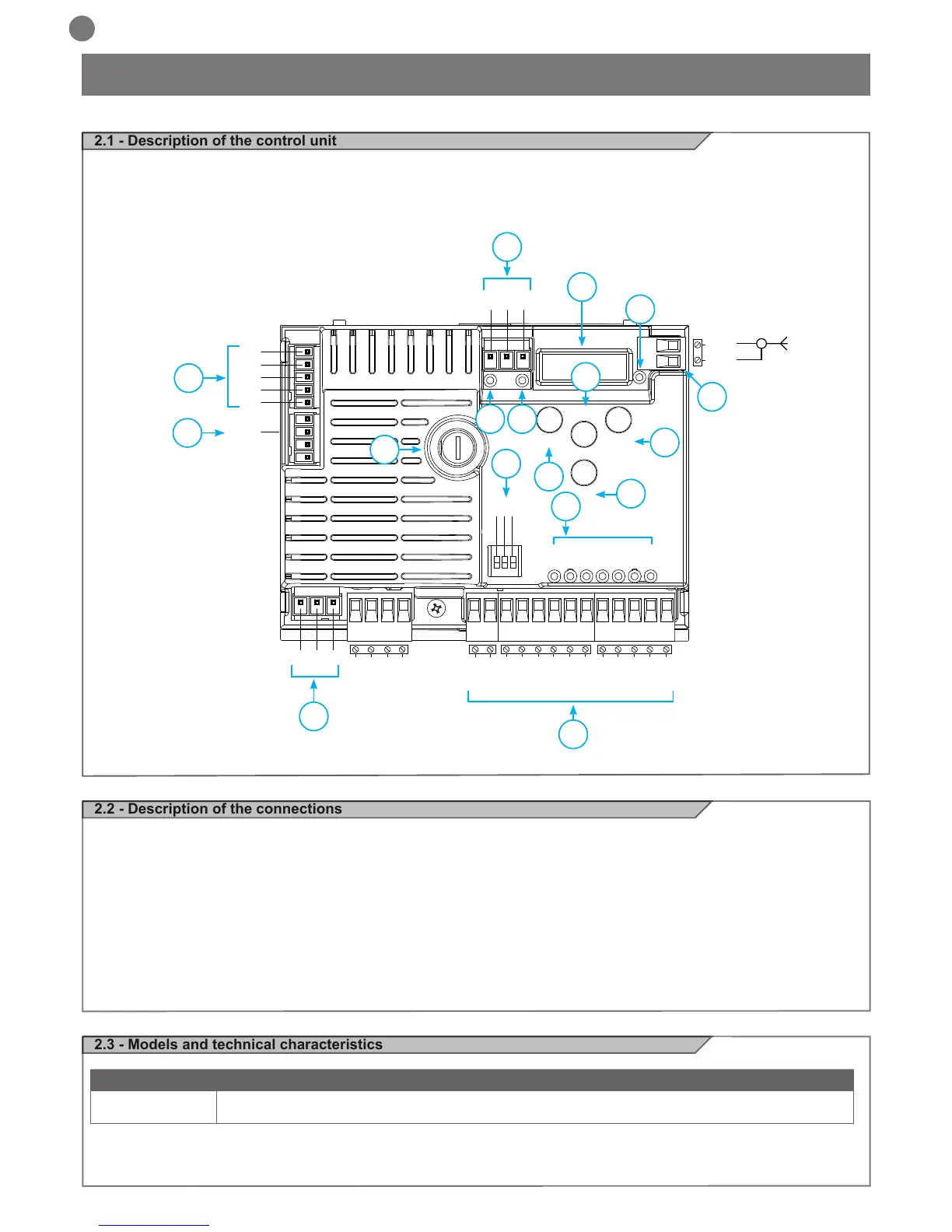
control of Key Automation motors for the electric opening and closure
of sliding gates, up-and-over doors and electromechanical barrier.


1- Motor power supply connections and encoder

3- 24Vdc and 24Vac output connections to controls and safety
devices
4- Connector for battery charger KBP
5- Limit switch connector
6- Functions display
7- Safety device dip switch
8- Fuse 2A slow-acting

input led
10- Limit switch indicator LED LSC
11- Limit switch indicator LED LSO

13- UP + button
14- MENU button
15- DOWN - button
16- Antenna
17- KEY led

has a display allowing easy programming and constant monitoring
of the input status; the menu structure also allows easy setting of
working times and operating modes.

CODE 
 24V control unit for sliding gates, up-and-over doors or electromechanical barrier
NEG
PH-POW
STOP
STOP
STOP
STOP
PH2
PH1
OPEN
CLOSE
PED
SBS
PH2
PH1
PH 2
COM
FLASH
IND
LED
SHIELD
UP
MENU
SBS
DOWN
(RADIO)
ANT
24 VAC
24 VAC
PH 1
OPEN
CLOSE
SBS
PED
COM
POWER SUPPLY
NEG
ENC
V +
M -
M +
BATTERY
LS 1
LS 2
KEY
COM
1
4
16
8
2
5
7
9
6
17
3
10
11
13
12
15
14

Other manuals for Key Automation CT102 24

Related product manuals