21
EN
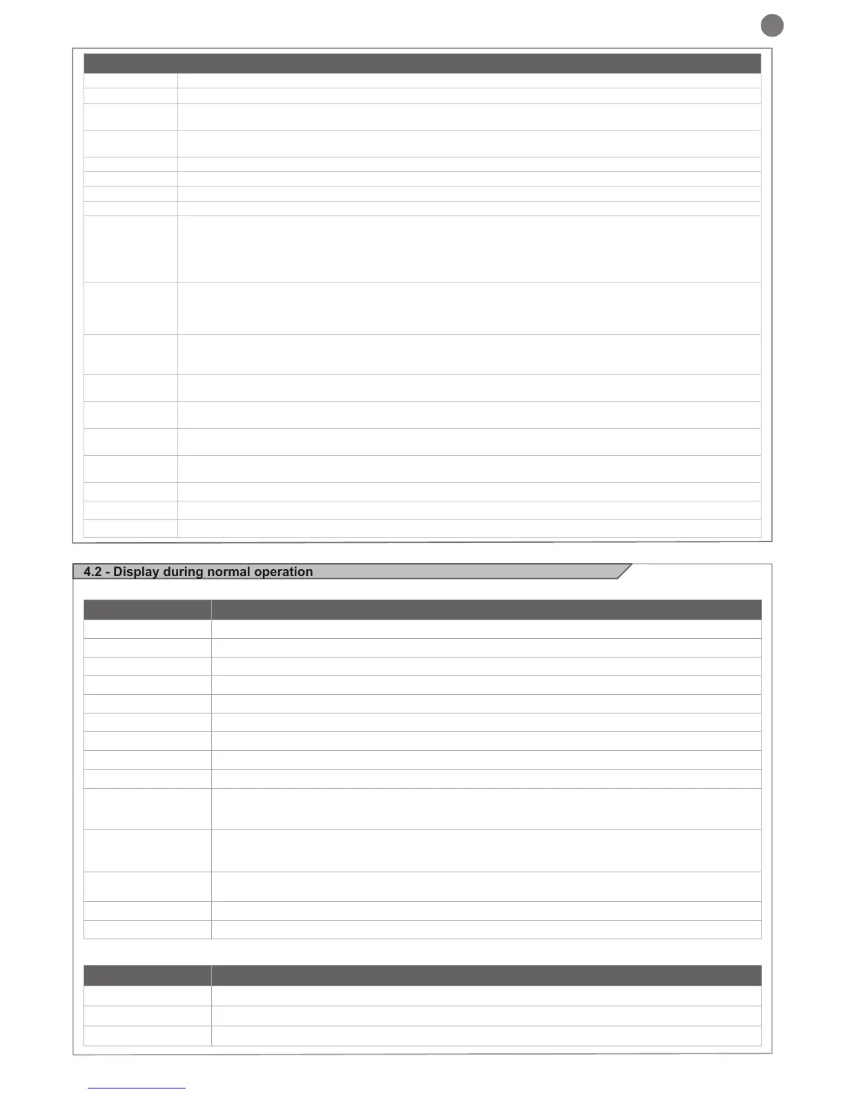
COM Common for the
Flashing light output 24Vdc (without regulation), maximum 25W
IND
IND output for gate open indicator light 24 Vdc not regulated 4W MAX / Electric lock output 12Vac, 15VA maximum
selectable with parameter IN.D.
LED
Courtesy light output 24Vdc (without regulation), maximum 25W, controllable also via radio ON-OFF command (radio
channel 4)
24 VAC Accessories power supply 24 Vac without regulation, 200 mA (with battery operation output not active)
24 VAC Accessories power supply 24 Vac without regulation, 200 mA (with battery operation output not active)
Accessories power supply negative
; phototest can be selected with parameter tp.h. 24 Vdc, 250 mA
system and disabling all functions, including Automatic Closure.
Input selectable with parameter Ed.m.
immediately; the automation system will continue opening when the contact is restored. In the event of intervention
on closure (parameter Ph.2. = 0) the device stops and on release re-opens.
immediately and reversing the travel direction.
OPEN
OPEN command NO contact between OPEN and COM
OPENS as long as the contact is held down
CLOSE
CLOSE command NO contact between CLOSE and COM
PED
command NO contact between PED and COM
Used to open the gate partially, depending on the software setting (not active in barrier/up-and-over mode)
SBS
command NO contact between SBS and COM
Open/Stop/Close/Stop command, or as set in the software
COM Common for the
Antenna - shield -
Antenna - signal -
--
OP
CL
SO
SC
HA
oP
OPD
Pe
-tC
Flashing dash counting in progress
-tP
Flashing dash counting in progress
L--
Learning started on limit switch (move the gate off the limit switch to continue the learning procedure) or lear-
ning stopped due to trip of safety device or motor inversion.
LOP
Learning opening
LCL
Learning closure
-.-
Limit switch CLOSED (one dot between the two lines)
tC.
Limit switch OPEN (a point to the right)
SO
No limit switch active (no dots present)

 Loading...


