EN
6
3 - PRELIMINARY CHECKS
Before installing the product, perform the following checks and in-
spections:
check that the gate, the door or the barrier is suitable for automation;
the weight and size of the gate or door and the balance of the barrier
boom must be within the operating limits specied for the automa-
tion system in which the product is installed;
check that the gate or door has rm, eective mechanical safety
stops;
make sure that the product xing zone is not subject to ooding;
high acidity or salinity or nearby heat sources might cause the pro-
duct to malfunction;
in case of extreme weather conditions (e.g. snow, ice, wide tempe-
rature variations or high temperatures), friction may increase, cau-
sing a corresponding rise in the force needed to operate the system;
the starting torque may therefore exceed that required in normal
conditions;
check that when operated by hand the gate, the door or the barrier
moves smoothly without any areas of greater friction or derailment
risk;
check that the gate, door or the barrier is well balanced and will the-
refore remain stationery when released in any position;
check that the electricity supply line to which the product is to be
connected is suitably earthed and protected by an overload and dif-
ferential safety breaker device;
the system power supply line must include a circuit breaker device
with a contact gap allowing complete disconnection in the condi-
tions specied by class III overvoltage;
ensure that all the material used for installation complies with the
relevant regulatory standards.
2.4 - List of cables required
• Electronic protection against short circuit and overload on the
FLASH, IND/ELEC and LED outputs
• Protection of 24VAC and PH-POW outputs via resettable fuses
• Automatic obstacle detection
• Auto-learning of travel length
• Disabling of unused safety inputs via dip switches: it is not
necessary to insert jumpers on the respective input terminals
(paragraph 4.2)
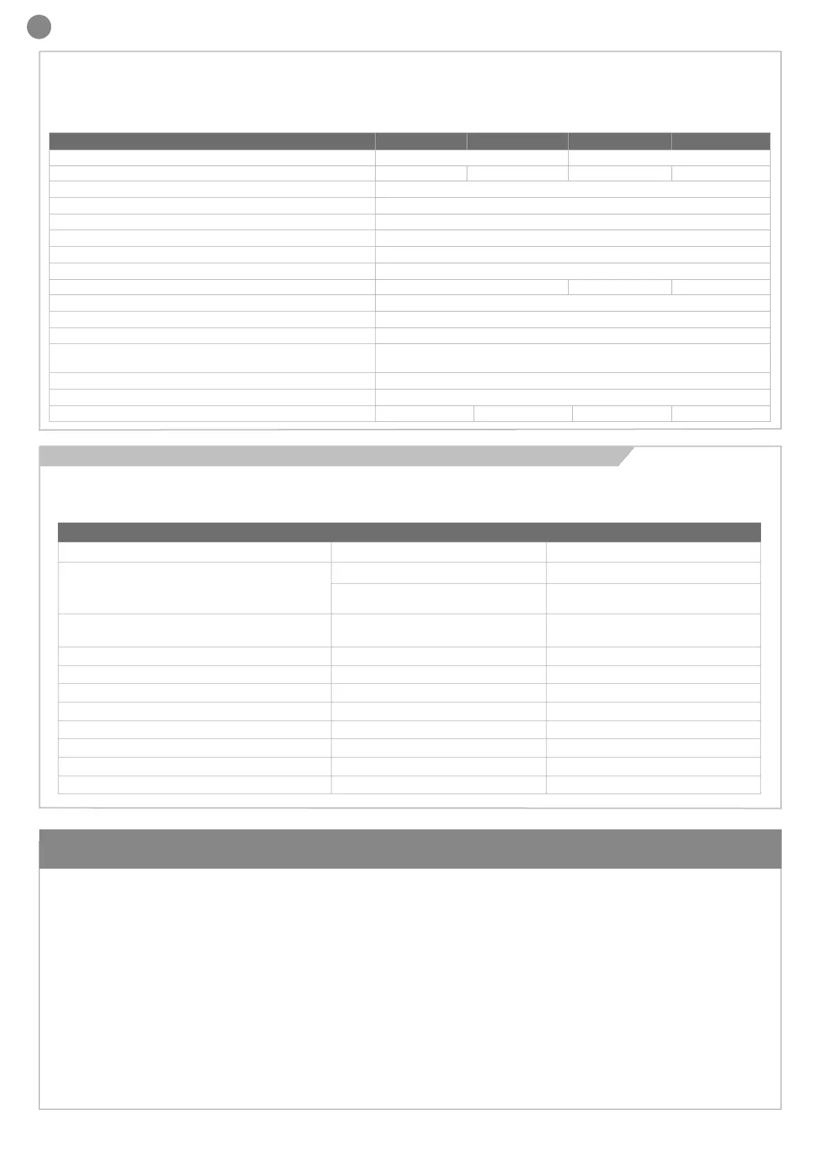
TECHNICAL SPECIFICATIONS CT20324 CT20324E CT20324L CT20324EL
Power Supply 230Vac (+10% - 15%) 50/60 Hz 115 Vac (+10% - 15%) 50/60 Hz
Nominal power
210W maximum 280W maximum 210W maximum 280W maximum
Maximum output current 24VAC 200 mA (24 VAC)
PH-POW maximum output current 250 mA (24 VDC non-regulated)
Maximum FLASH output power 15 W (24 VDC)
Maximum LED output power 15 W (24 VDC)
Maximum power for the “IND/ELEC” output 5 W (24 VDC) / 15 VA (12 VDC)
Accessory fuses 2.0 AT (timed)
Power line fuses 1.6 AT 3 AT 5 AT
Integrated radio receiver 433.92 MHz OOK
Antenna wire or cable antenna RG58
Number of saved transmitters 150
Can be used in saline, acidic or explosive atmosphere
environments
NO
IP protection class IP54
Overall dimensions 222 x 110 x 275 H mm
Weight 3,87 kg 4,46 kg 3,87 kg 4,46 kg
ELECTRIC CABLE TECHNICAL SPECIFICATIONS
CONNECTION CABLE MAXIMUM PERMITTED LIMIT
Control unit power transformer input
3 x 1,5 mm² if less than or equal to 20 m
3 x 2,5 mm²
if greater than 20m, (connect the earth
wire near the control unit)
Flashing light (FLASH)
Courtesy light (LED)
3 x 0.55 mm² 20m
Antenna RG58 cable 10 m (recommended < 5 m)
Electric locking (IND/ELEC) 2 x 1.5 mm² 10m
Photocells (transmitter) 2 x 0.55 mm² 20m
Photocells (receiver) 4 x 0.55 mm² 20m
Safety edge 2 x 0.55 mm² 20m
Key switch 4 x 0.55 mm² 20m
Motors power supply (M1 and M2) 2 x 1.5 mm² 10m
Encoder cables 4 x 0.55 mm² 10m
The following table shows the cables necessary for connection of
the various devices in a typical system.
The cables must be suitable for the type of installation; for example,
we recommend a cable type H03VV-F for installation indoors or
H05RN-F/H07RN-F if installed outdoors.

 Loading...