EN
7
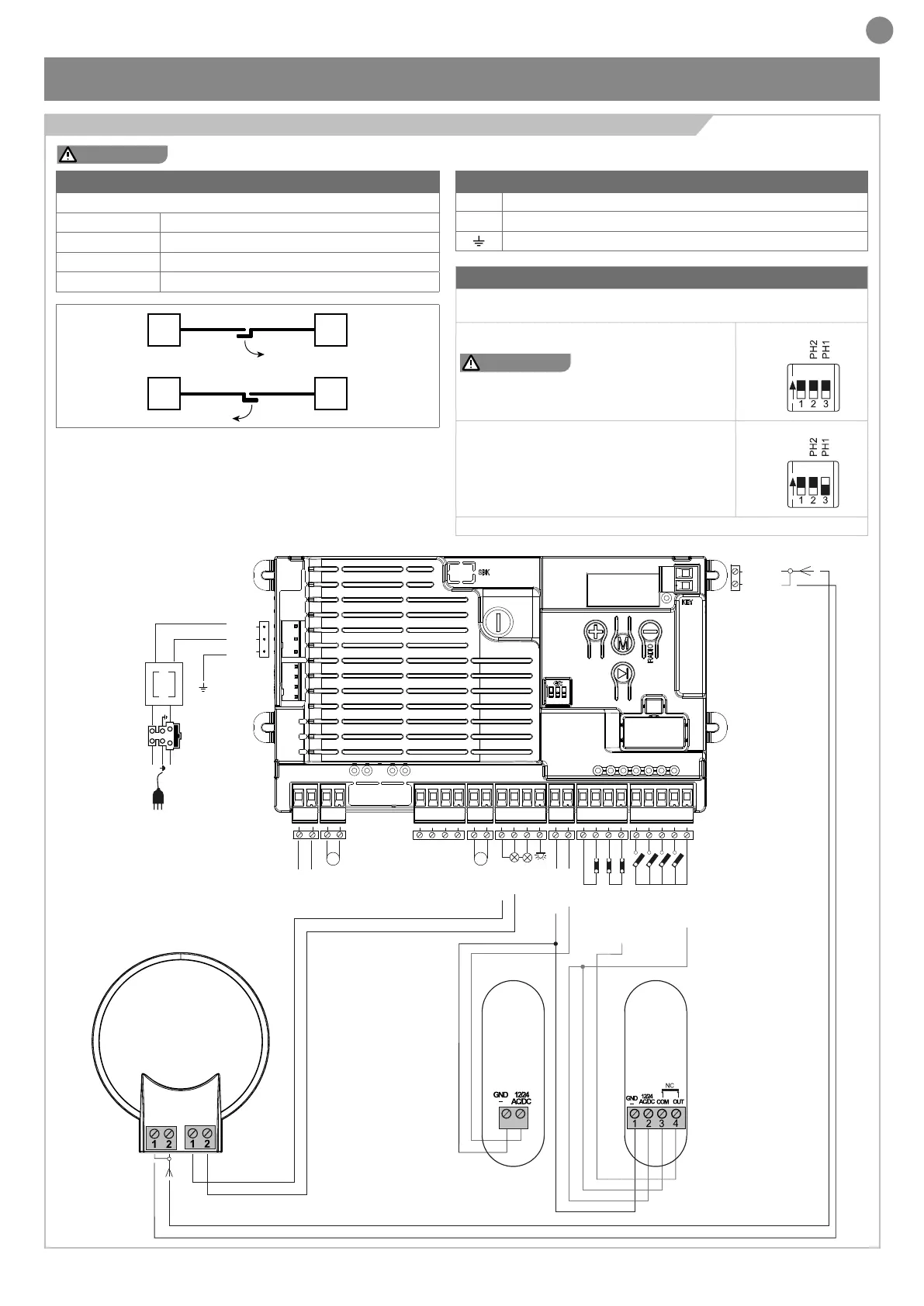
4 - PRODUCT INSTALLATION
WARNING !
Before making the connections, ensure that the control unit is not powered up.
4.1 - Electrical connections
DIP SWITCH
Set on “ON” to disable inputs EDGE, PH1, PH2
This procedure avoids to bridge the terminal board inputs.
WARNING !
with the dip switch ON,
the safety devices are disabled.
ON
EXAMPLE: With only 1 photocell
connected set EDGE and PH2 to ON
ON
To disable, follow the procedure at paragraph 4.2
MOTORS CONNECTION
Power supply connection terminal board
M1 + Power supply of motor M1 +
M1 - Power supply of motor M1 -
M2 + Power supply of motor M2 +
M2 - Power supply of motor M2 -
M1
M1
M2
M2
POWER SUPPLY CONNECTOR
L Power supply live 230 Vac (120 Vac) 50-60 Hz
N Power supply neutral 230 Vac (120 Vac) 50-60 Hz
Earth
N
T1,6A
L
230Vac
50/60Hz
PHPOW
OUTPUT LED
OPEN
PHOTOCELL 1
PHOTOCELL 2
CLOSE
PEDESTRIAN
STEP BY STEP
COMMON
EDGE/EDGE
INDICATOR
NEGATIVE
24 VAC
24 VAC
M1 M2
FLASH
COM
BATTERY
COMMON
FLASH
SHIELD
ANT
COMMON
FLASH
PH1
RX
2
1
PH1
TX
SHIELD
ANT
POWER
SUPPLY
ON
EDGE
PH2
PH1
v+
ENC M1
ENC M2
NEG