EN
8
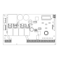
ELECTRICAL CONNECTIONS FOR PHOTO1 AND PHOTO2
PHOTOTEST
OUTPUT LED
OPEN
PHOTOCELL 1
PHOTOCELL 2
CLOSE
PARTIAL
STEP BY STEP
COMMON
EDGE/EDGE
INDICATOR
NEGATIVE
24 VAC
24 VAC
M1+
M1-
M2+
M2-
COM
FLASH
+ ALIM. ENCODER
- ALIM. ENCODER
ENCODER 1
ENCODER 2
EDGE
EDGE
PH2
PH1
OPEN
CLOSE
SBS
PAR
COM
SHIELD
ANT
POWER
SUPPLY
GND
12/24 AC/DC
GND
12/24 AC/DC
COM
OUT
NC
COM
OUT
GND
12/24 AC/DC
GND
12/24 AC/DC
TX RX
PHOTO-2
NC
2
3
4
1
1
2
2
3
4
1
1
2
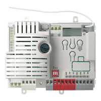
ELECTRICAL CONNECTIONS
FOR ENERGY SAVING
WARNING !
To enable
STAND BY
see
paragraph 5.1, point 12. Only during this fun-
ction PHOTOTEST is not possible
PHOTOTEST
OUTPUT LED
OPEN
PHOTOCELL 1
PHOTOCELL 2
CLOSE
PEDESTRIAN
STEP BY STEP
COMMON
EDGE/EDGE
INDICATOR
NEGATIVE
M2
M2+
M2-
COM
FLASH
IND ELEC
LED
NEG
PH POW
EDGE
EDGE
PH2
PH1
OPEN
CLOSE
SBS
PED
COM
COMMON
FLASH
PH1
RX
PH1
TX
2
1
PH2
RX
PH2
TX
2
1
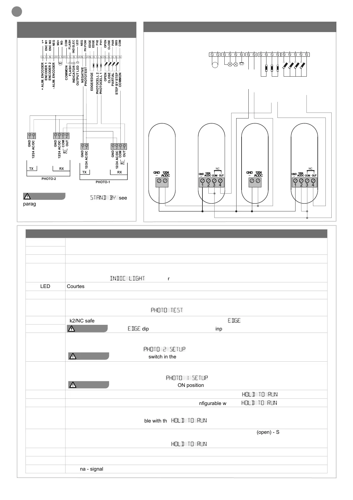
SAFETY AND CONTROL DEVICE CONNECTORS
24 VAC
Accessory power supply 24VAC non-regulated 200mA MAX; not active during battery operation
24 VAC
COM Common positive for FLASH - IND/ELEC - LED and accessories outputs
IND/ELEC
IND, gate open warning light output, 24VDC 5W MAX
ELEC, electric lock output 12VDC 15VA MAX
selectable with the
INDIC LIGHT
parameter
LED Courtesy light output, 24VDC non-regulated 15W MAX also controllable via radio remote control
NEG Negative power supply for accessories
PH-POW
Positive power supply for PH1 and PH2 photocells;
operating mode congurable with the
PHOTO TEST
parameter
EDGE/EDGE
8k2/NC safety edge contact input; operating mode congurable with the
EDGE
parameter
WARNING !
with the
EDGE
dip switch in the ON position the input is always disabled
EDGE/EDGE
PH2
PH2 opening photocell NC input; at any time during opening/closing, the intervention of the photocell (opening of the
contact) causes the movement to immediately stop. Closing the contact restores the opening operation. The operating
modes can be congured with the
PHOTO 2 SETUP
parameter
WARNING !
with the PH2 dip switch in the ON position the input is always disabled
PH1
PH1 closing photocell NC input; at any time during closing, the intervention of the photocell (opening of the contact)
causes blocking and reversal of the direction of travel. While PH1 is active it is not possible to close the gate. The
operating modes can be congured with the
PHOTO 1 SETUP
parameter
WARNING !
with the PH1 dip switch in the ON position the input is always disabled
OPEN
NO OPENING command input; MAN PRESENT function congurable with the
HOLD TO RUN
parameter
CLOSE
NO CLOSING command input; MAN PRESENT function congurable with the
HOLD TO RUN
parameter
PAR
NO PARTIAL OPENING command input;
MAN PRESENT function congurable with the
HOLD TO RUN
parameter
SBS
NO STEP-BY-STEP command input (SBS); upon each activation the commands AP (open) - ST (stop) - CH (close)
are executed in succession; the operating modes are congurable with the SBS SETUP parameter.
MAN PRESENT function congurable with the
HOLD TO RUN
parameter
COM Common positive inputs PH2, PH1, OPEN, CLOSE, PAR, SBS
SHIELD Antenna - shield
ANT Antenna - signal
 Loading...