11
EN
PHASE DESCRIPTION
1 Press the MENU button a number of times corresponding to the parameter to be changed (TAB. 3 - P. 51)
2 LED L1 emits quick ashes followed by a pause corresponding to the parameter to be changed
3 Press and hold down MENU for more than 3 seconds
4 The LED L1 remains o
5 Release the MENU key
6
The LED L1 will start emitting long ashes, the number of ashes matches the maximum settable parameter value. At the end of
the last ash the procedure ends without any parameter change
7 Briey press the MENU button upon the ash corresponding to the desired parameter value
8 If the procedure is successful, LED L1 will emit a long ash, otherwise it will ash repeatedly at a fast rate
PHASE DESCRIPTION
1 Press and hold the MENU button until the LED L1 lights up and then goes o
2 Release the MENU key
3 LED L1 will start emitting long ashes
4 Press the MENU button again upon the 3rd ash
5 If the procedure is successful, LED L1 will emit a long ash, otherwise it will ash repeatedly at a fast rate
4.13 - Changing a control unit parameter
4.14 - Control unit parameter resetting
4
The door must perform a slow-speed opening
If the door closes, press the button again to stop it then press it again to reverse the direction. This procedure can only
be successful if the rst operation is an opening stroke and it ends with the slider impacting the mechanical stop previ-
ously positioned
5
The door reaches full opening position as the slider reaches its mechanical stop, stops for a second and then restarts in the closing
direction until the operation is complete
6 The values are stored
7
Perform AT LEAST one second full opening operation and one second full closing operation from the limit stop point without
breaks, to allow the control unit to store the motor stress along the travel
8
If the automation system fails to complete the operation, check that there are no mechanical jams along the travel, the balancing
of the door and possibly change and reduce the obstacle sensitivity parameter
9
To reset opening and closing values:
press and hold the MENU button until the LED L1 lights up and then goes o.
Release the MENU button. LED L1 emits long ashes.
Press the MENU button again upon the:
5th ash for the HALO 800 motor
6th ash for the HALO 1200 motor
If the procedure is successful, LED L1 will emit a long ash, otherwise it will ash repeatedly at a fast rate
Repeat the procedure from point 4 above
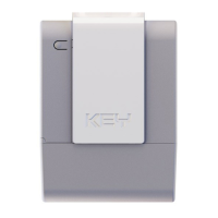
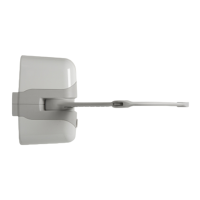
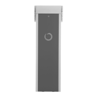
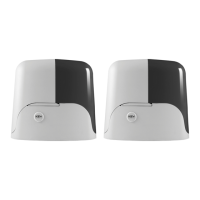
If you have a KUBE PRO wireless module, connect it to the control
unit (FIG. 49, 50) and follow the instructions on the screen.
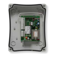
If you have a DYL cable module, connect it to the control unit and
follow the instructions on the screen.
Otherwise proceed as described below:
ATTENTION !
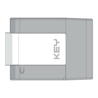
4.15 - Hole for access control mechanism
Close the garage door (controlled by the motor); using a pencil,
mark the position of the slider on the opposite side with respect to
the door. Release the slider, then drill a 10 mm hole in the centre of
the rail where marked (FIG. 51).
Check the ecient operation of the mechanism by closing the door
manually, resetting the slider and trying to open the garage door
manually.
 Loading...