10
EN
4 - PRODUCT INSTALLATION
4.1 - Installation
4.2 - Installing the rear xing bracket with inward opening
4.3 - Installing the front xing bracket with inward opening
The xing position of the rear bracket is determined according to the
graph (Fig. 4).
Important: installations where the values of “A” and “B” (Fig. 4) are
as similar to each other as possible are preferred (l.o.= optimal line).
Identify dimension C found and trace a horizontal line that
determines the value of dimension B (*) as shown in the example
of g. 4b; the meeting point with line “l.o.” (optimal line) determines
the value of the angle of maximum opening; from this point, trace a
vertical line as shown in the example of g. 4b to determine the value
The front bracket must be xed to the door according to dimension
“E” of Table 1 (Fig.5).
Note: If you mount the closing limit switch, reduce the value “E” of
of dimension A.
If the angle found does not correspond to the requirements, adapt
dimension A and if necessary dimension B, so they are similar.
(*) Do not use values of dimension B below the line “l.s.”
If necessary, cut the rear bracket (Fig. 7) to obtain the value “B”, then
weld the xing bracket to the wall.
Secure the bracket to the wall using welding, screws or bolts (not
included).
40 mm.
The front bracket must be xed as the same height as the rear
bracket (Fig.8).
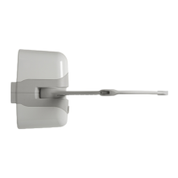
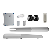
Before proceeding with the installation, check the integrity of the
product and that all components are present in the package (Fig. 3).
Also make sure that the mounting area of the gear motor is
Also check that the gearmotor’s installation zone is compatible with
its overall dimensions (Fig.1).
Check the opening angle permitted by the bracket xing points using
the graph in Fig.4 for inward opening. For outward opening, refer to
the graph in Fig.4.1.
Fig.6 shows a typical installation:
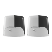
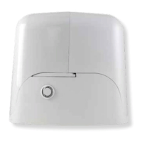
Gear motors (1)
Photocells (2)
Columns for photocells (3)
Flashing light with antenna (4)
Key switch or digital keypad (5)
Control unit (6)
Pressure-sensitive edge (7)
The automation system must be equipped with a pressure-sen-
sitive edge protecting all possible crushing points (hands, feet,
etc.) in accordance with the requirements of the EN 13241-1
standard.
The gate must have limit stops in the open and closed posi-
tions which prevent it from travelling over the permitted limits.
The installer must verify that the working temperature range
stated on the automation device is suitable for the location
where it is installed.
ATTENTION !
ATTENTION !
ATTENTION !
4.5 - Installing the front xing bracket with outward opening
4.4 - Installing the rear xing bracket with outward opening
The EXRB accessory is required for outward opening. Measure di-
stance “C1”. If distance “C1” is 130 mm or less, refer to Fig. 5.1A; if
it is more than 130 mm, refer to Fig 5.1B.
To establish distance “B1” draw a horizontal line from the value of
distance “C1” (Fig.4.1); the point where the areas of the graph meet
provides the possible values of point “A1”.
After fastening the rear xing bracket to the wall, screw on the optio-
nal brackets EXRB as shown in Fig. 5.1A or Fig. 5.1B.
The front bracket must be xed to the leaf in accordance with distan-
ces “E1” (Tab.2, Fig.5.1) and must be xed at the same height as
the rear bracket (Fig.8).
 Loading...