- 2 -
P2P
2P2
2. Installation and Wiring
2-1 Installation
• Tightening torque for the mounting holes: 0.63 N·m (M3 screw)
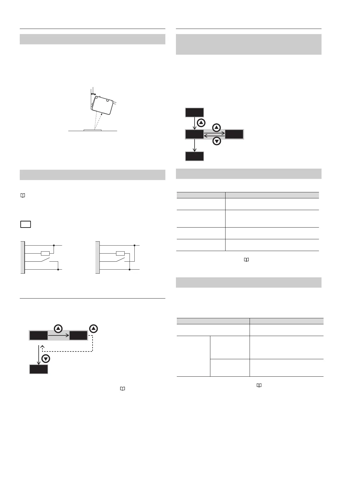
• If the workpiece contains a glossy surface that could interfere with stable
detection, tilt the sensor approx. 15° to 20°. If tilting the sensor does not
improve detection, please attach the reflection canceling attachment
(LR-WA2).
• High-frequency light, such as that from an inverter fluorescent lamp, entering
the receiver directly or after reflecting from the workpiece may lead to
malfunctions. In this situation, implement countermeasures such as installing a
light shielding plate or changing the product's installation position.
2-2 Wiring
Either an NPN or a PNP output can be selected during the initial setup of this
product.
"3. Initial Settings (NPN/PNP Selection)" (page 2)
Independently insulate any unused I/O wires.
= Load (input device)
When NPN output is selected
3. Initial Settings (NPN/PNP Selection)
When the power is turned on for the first time after purchase, or initialization is
performed, the initial setting (NPN/PNP selection) is required as shown below.
* After the initial setup is complete, "NPN/PNP selection" setting cannot be
changed. To change this setting, initialize the sensor. "7-2 Initialization"
(page 5)
4. Basic Settings
4-1 Output Logic Selection
(N.O./N.C. Selection)
Set the output logic to N.O. or N.C..
• ()*: Turns the output on when the registered condition is met (turns the
output on when light is received) *.
• ()*: Turns the output on when a condition other than the registered
condition is met (turns the output on when light is not received) *.
* The condition within parentheses indicates the condition when super I mode is
selected.
4-2 Detection Mode
This sensor contains four detection modes.
Detection mode Explanation
Auto
(default)
When adjusting the sensitivity, the optimal mode
is automatically selected between C+I or C.
C+I mode
Detection is performed according to the color
components (R, G, B) and illumination (the
received light intensity).
C mode
Detection is performed according to the color
components (R, G, B) only.
Super I mode
Detection is performed according to the
illumination (the received light intensity) only.
* To change the detection mode, see "8 Settings" (page 6).
4-3 Spot/Mode Selection
This product is equipped with a [2-Spot Mode] , which utilizes 2 spots for
detection.
When using the [2-Spot Mode], select one of the detection methods below. Note
that the sensor operates in [C+I mode] when in [2-Spot Mode].
Spot Description
1-Spot Mode (default)
Detection based off of 1 spot. Utilized
for standard target detection.
2-Spot Mode
Difference
Monitoring
Detection based on the difference in
appearance between the 2 spots.
Typical tuning operation is not
required.
2-Point Matching Detects based on the degree of
conformity of both spots to a
calibrated reference.
* For details on calibration in [2-Spot Mode], refer to "6. Sensitivity Adjustment
(2-Spot Mode) " (page 5).
When PNP output is selected
1, brown
4, black
2, white
3, blue
10 … 30 V
0 V
PNP NPN
PAQ
PA%
RUN
3s or more
3s
RUN
15 to 20°
3s or more
1, brown
4, black
2, white
3, blue
10 … 30 V
0 V
RUN
 Loading...