Module 2
Basic Measurement
2-9
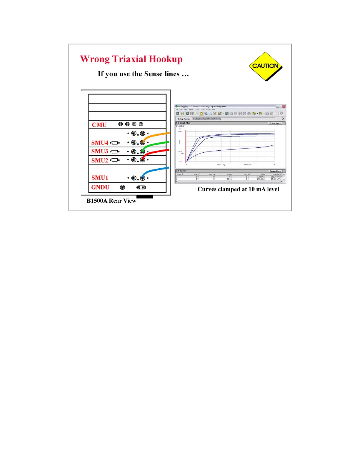
This picture shows the triax cables connected to the right set of connectors which is wrong.
The 4 triax cables must be connected to the left set of connectors (FORCE).
You will likely see this type of erroneous response with clamping at 10 mA (no trace above 10 mA
even though compliance is set much higher). Also you may see the response with notches at 10 mA
level.
The effect is magnified when the SMU measurement ranging is set to AUTO.
This curve was produced using your training class MOS device and the IDVD setup.
No error was seen until the ranging was changed from FIXED 100 mA to AUTO. Then it was
evident that the cables were hooked up improperly.

 Loading...


