168 Keysight FieldFox Handheld Analyzers Service Guide
Repair and Replacement Procedures
Processor Upgrade Procedures
7-
14.Place the RTC board onto the System board shield and secure with the two
screws. Torque to 9 in-lbs.
15.Remove the System board to FPIB cable (W14) from the old A5 System
board and install it on the new board.
16.Reinstall the I/O side panel. Refer to “Replacing the I/O Side Panel, Doors,
and Gasket” on page 120.
17.Perform the steps under “Final Assembly Procedure” on page 164.
18.Change the nameplate, remove old nameplate. Refer to Figure 7-13 on
page 124. Choose the appropriate model number nameplate overlay for
your analyzer, remove the protective baking to expose the adhesive, and
adhere it in the location shown. Refer to Figure 7-41 for the new
nameplate with red Keysight logo.
19.Proceed “Post-Repair Procedures” on page 165. Download and install the
latest Firmware for the CPU2 from Fieldfox Series Firmware Updates.
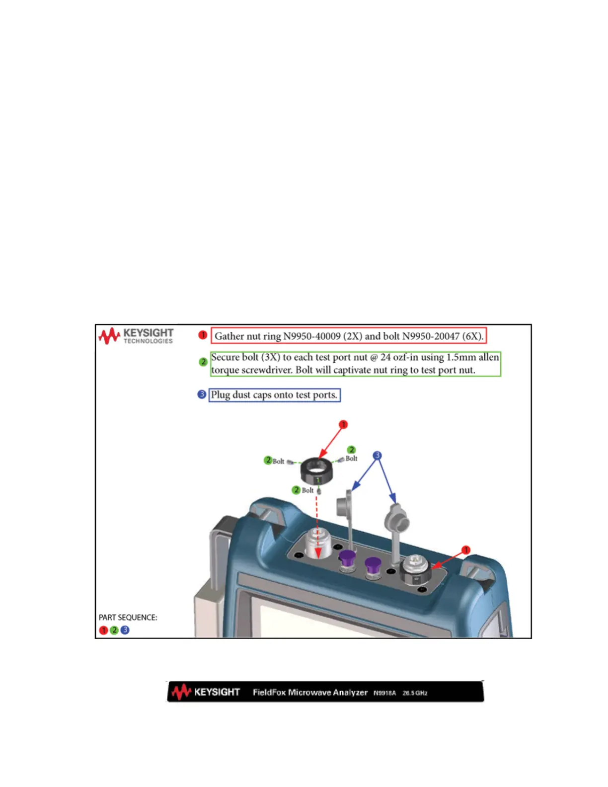
Figure 7-40 Installing the nut ring
Figure 7-41 New Keysight Nameplate
 Loading...


