07 | Keysight | FieldFox Handheld Analyzers - Configuration Guide
FieldFox RF and Microwave (Combination) Analyzer FAQs (continued)
Question Answer
14. Is Spectrum Analyzer Trace
Recording and Playback
standard or an option?
– Spectrum Analyzer mode (Option 233) does not include Trace Recording and Playback by default. To obtain
this capability in SA mode, Option 236 Interference Analyzer and Spectrogram needs to be purchased.
– RTSA mode (Option 350) does include Trace Recording and Playback by default in RTSA mode.
– Purchasing RTSA mode (Option 350) does not enable Trace Recording and Playback in SA mode (Option 233).
Trace record/playback features
SA mode
SA & Interference Analyzer
Options 233 and 236
RTSA mode
RTSA
Option 350
Record and playback spectrum traces Yes Yes
Save trace data with GPS time stamp over time Yes Yes
Record and playback spectrogram data Yes No
*
Frequency mask trigger Yes No
* RTSA trace recordings can be recalled and played back in SA mode Spectrogram. This has the added benefit that the
measurements are shown ‘slower’, making it easier for the human eye to decipher the signal content.
Item Description/Options Quantity
FieldFox Combo analyzer: required Option 210, 233. Recommended: 235, 307
SA analyzer: required: Option 220, recommended: 235, 307
2
Power splitter 11667A (Type-N) or 11667B (3.5 mm) or 11667C (2.4 mm) 1
Type-N(m) to Type-N(m) adapter N9910X-850 (for use with 11667A or Type-N systems) 1
Trigger cables
1
N9910X-712, SMA(m) to BNC(f)
N9910X-713, SMB(m) to BNC(m)
2 of each
Total of 4 cables
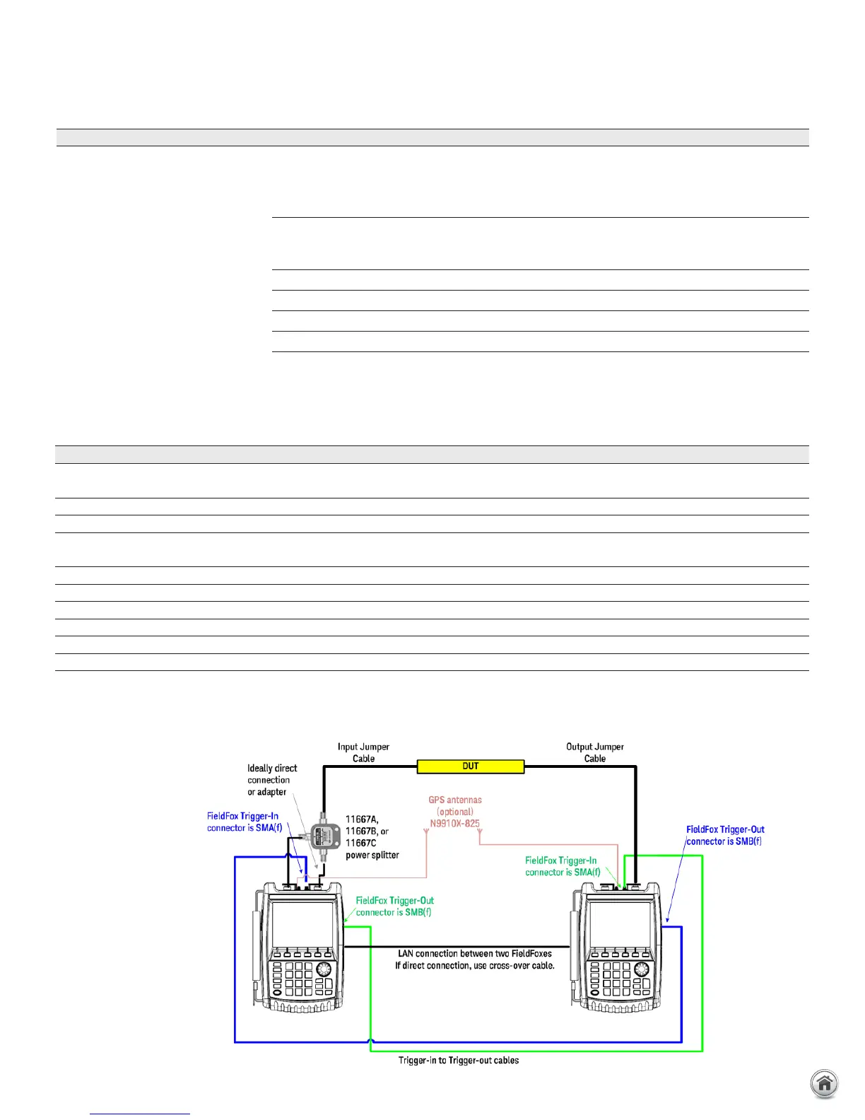
RF test cable Connecting FieldFox source port 1 to power splitter input 1
RF test cable or adapter Connecting power splitter output arm to FieldFox port 2 1
RF jumper cable or adapter Power splitter output arm to DUT input 1
RF jumper cable or adapter DUT output to FieldFox receiver port 2 1
LAN cable LAN cable to connect FieldFoxes directly, or the analyzers must be on the LAN 1
N9910X-825 GPS antenna, recommended. Necessary if Option 307 is ordered. 2
1. The trigger cables and LAN cables must be at least as long as the separation distance between the two ends of the DUT.
ERTA System Typical Configuration
ERTA system diagram
 Loading...


