MAC Demo Software
Setup tab
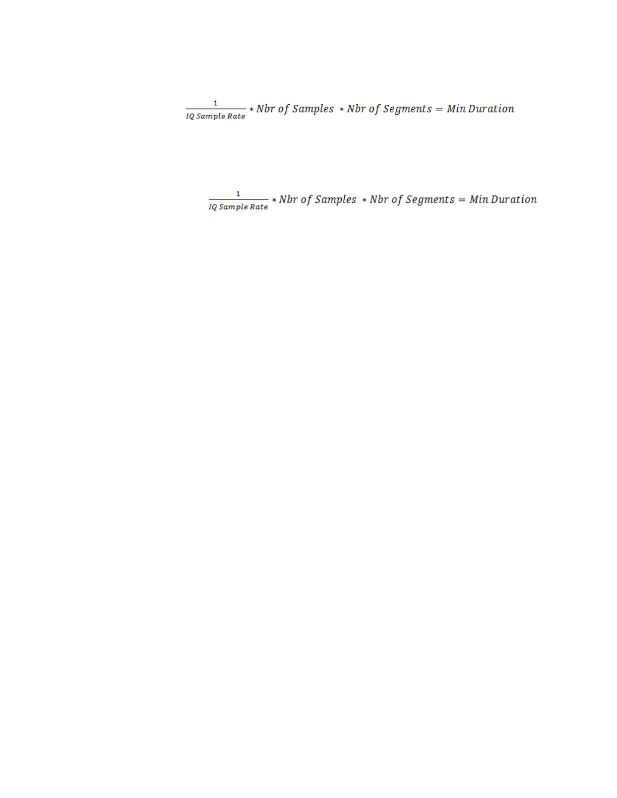
G – Nbr of Samples is the number of samples per segment that the digitizer will
acquire.
H – Nbr of Segments is the number of segments in segmented memory mode that will
be acquired (one segment per occurrence of trigger event).
I – Min Duration is the minimum duration of acquisition assuming back to back triggers
with no gaps.
This field will update if you click on it. It is not auto-updated due to dependencies on
other GUI controls, each of whih would try to update the text in this label.
J – IQ Sample Rate is the effective sample rate at which I&Q pairs get stored into the
M9703A digitizer’s RAM. This is a configuration parameter for the –DDC option which
is a required option for MAC. This property can also be set as an IF bandwidth rather
than sample rate by changing properites in Utiltiy…Properties menu (see separate
documentation on Properties dialog)
K – Offset is the DDC center frequency. It determines where in the M9703As
passband that the IF signal is centered.
L – Source (trigger) is the input that drives the trigger for the acquisition(s) by the
M9703A digitizer. Options include External1 and M-Channel1…Channel8 (where M
stands for master module in a multi-module set).
M – Type (trigger) is used to specify what criteria the trigger will fire on. The options
include Edge and Magnitude. The magnitude trigger is NOT compatible with
segmented memory as it is part of the DDC and that logic exists downstream of the
trigger subsystem in the M9703A architecture. It should also be noted that the MAC
software has intelligence built into auto trigger if a timeout occurs with the specified
trigger (timeout is set in the Utility…Preferences dialog) and Nbr of Segments = 1.
Note: you cannot software trigger the M9703A with more than one segment
configured.
N – Level (trigger) is used to specify the voltage level for an edge trigger type.
O – Slope (trigger) is used to distinguish between rising and falling edges when trigger
type is set to edge.
P – Option string is the option string literal that is passed to the M9703A IVI-COM
driver on initialization. Do NOT change this unless you have consulted the MD1 IVI-
COM driver help and clearly understand the syntax because changes can cause
seemingly unusual or unpredictable behavior. The default is: DriverSetup=
Trace=false, CAL=0, model=M9703A
26 Keysight Y1299A-003 MAC Reference Solution Startup Guide