MAC Demo Software
Setup tab
Keysight Y1299A-003 MAC Reference Solution Startup Guide 25
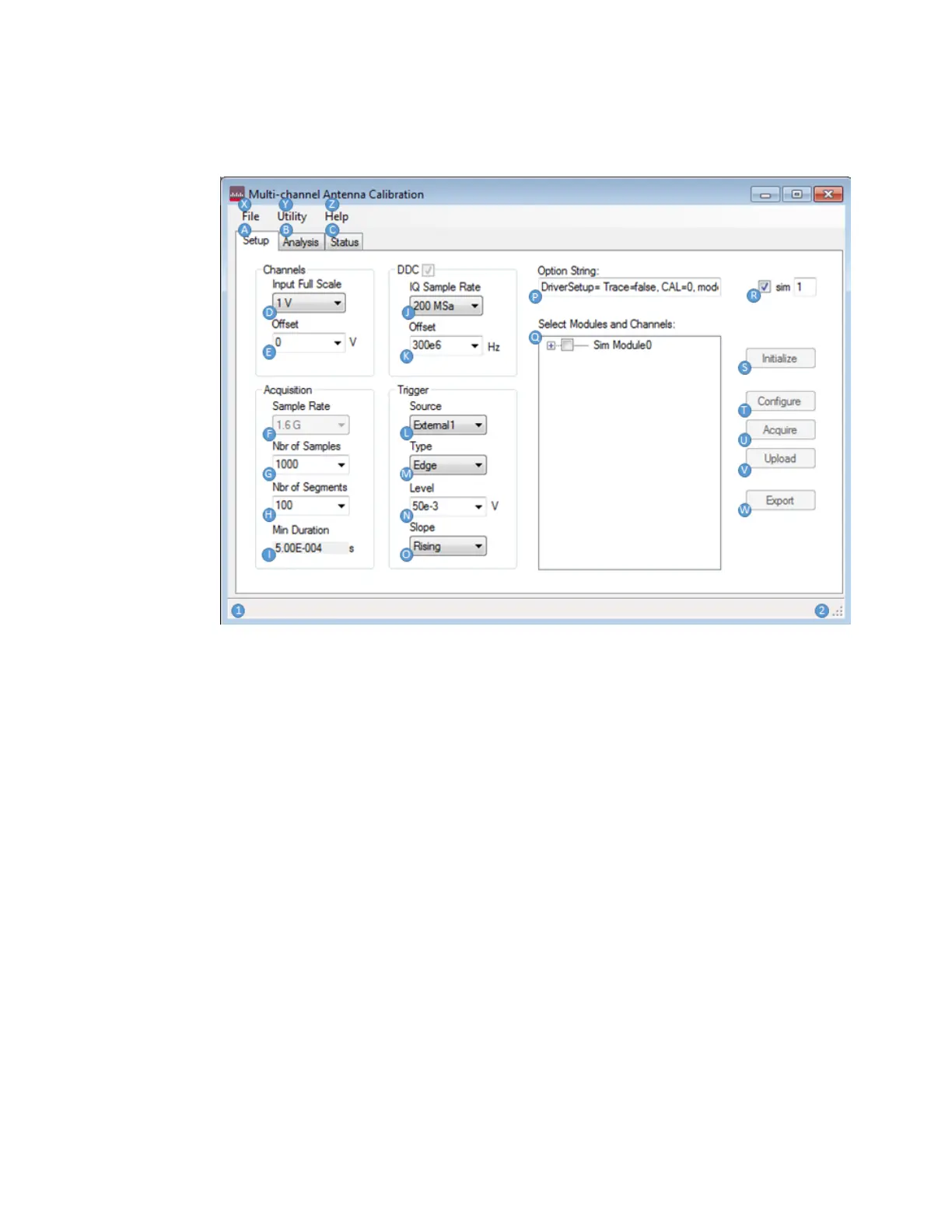
Setup tab
A – Setup tab is used to configure and control the data acquisition of one or more
M9703A IF digitizers.
B – The Analysis tab is used to view and parameterize the measurement interval
windows that are used (based on the number of samples) for cross channel ratios.
C – Status tab displays information about active M9703A digitizer sessions, and
tracks state execution details with time tags during the data acquisition process.
D – Input Full Scale range selection allows the user to choose a full scale range in
Volts for the M9703A(s). This is the range of voltages (centered at Offset) over which
the 12-bit ADC quantization steps occur. For M9703A this is either 1V or 2V.
E – Offset voltage is the center of the range covered by the ADC quantization steps.
Default is 0V (0V DC offset).
F – Sample Rate is the rate at which the raw ADC samples are made. This is always
1.6 Gsa/s for the M9703A with –SR2 sampling rate option (only supported sample
rate for MAC currently).