90 Keysight 34921A-34925A User’s Guide
Modules Pollution Degree 1 Pollution Degree 2 Transients
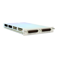
Multiplexer 34925A
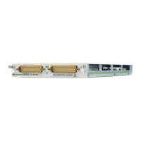
Terminal Block 34925T
40/80 channels, 1MHz
±80Vpeak
1
0.02A
2
1.6VA/channel
3
Volt-Hertz limit: 10
7
Initial closed channel resistance
4,5,6
:
<700
40/80 channels, 1MHz
±80Vpeak
1
0.02A
2
1.6VA/channel
3
Volt-Hertz limit: 10
7
Initial closed channel resistance
4,5,6
:
<700
1000Vpk
The overcurrent protection devices will be rated, or the snubber circuits will limit the current, according to:
Overcurrent Protection Device Rating per Application Voltage (1.6VA max) = 0.02A
1. Peak voltage, channel-to-channel or channel-to-earth.
2. DC or peak AC current.
3. Limited to 6 W of channel resistance power loss per module.
4. With input protection resistors: 2 x 100
±5%; 0.5W; TC = ±200 ppm/°C. The series resistance of the 34925A limits the use of the 100
range.
5. Into analog bus. System errors are included in the internal DMM measurement accuracy specifications.
6. Channel resistance is typically < 1.5
but can go as high as 50 when a channel is used in measurement applications with < 10 mA load
current. Increased relay channel resistance for measurements with load currents below 10 mA can occur on cards that have been out of
service or following relay inactivity for periods of greater than 1 week. Switching relays for 2K cycles prior to use may reduce the variation in
channel resistance. Applies to the 34921A and 34922A. Keysight recommends the use of 4-wire Ohms for resistance measurements. For
high accuracy voltage measurements, select the DMM input resistance setting of >10 G ohms to minimize the impact of relay contact
resistance.