EasyManua.ls Logo

Keysight 34921A User Manual

Keysight 34921A
62 pages
To Next Page IconTo Next Page
Page #1 background imageLoading...
Page #1 background image
Artisan Technology Group is your source for quality
new and certied-used/pre-owned equipment
FAST SHIPPING AND
DELIVERY
TENS OF THOUSANDS OF
IN-STOCK ITEMS
EQUIPMENT DEMOS
HUNDREDS OF
MANUFACTURERS
SUPPORTED
LEASING/MONTHLY
RENTALS
ITAR CERTIFIED
SECURE ASSET SOLUTIONS
SERVICE CENTER REPAIRS
Experienced engineers and technicians on staff
at our full-service, in-house repair center
WE BUY USED EQUIPMENT
Sell your excess, underutilized, and idle used equipment
We also offer credit for buy-backs and trade-ins
www.artisantg.com/WeBuyEquipment
REMOTE INSPECTION
Remotely inspect equipment before purchasing with
our interactive website at www.instraview.com
LOOKING FOR MORE INFORMATION?
Visit us on the web at www.artisantg.com for more
information on price quotations, drivers, technical
specications, manuals, and documentation
Contact us: (888) 88-SOURCE | sales@artisantg.com | www.artisantg.com
SM
View
Instra
Question and Answer IconNeed help?

Do you have a question about the Keysight 34921A and is the answer not in the manual?

Keysight 34921A Specifications

General IconGeneral
Model34921A
CategoryControl Unit
ManufacturerKeysight Technologies
Module FunctionMultiplexer
Maximum Voltage300 V
Maximum Current1 A
Relay TypeElectromechanical
Connector TypeScrew terminal
Number of Slots1
Storage Temperature-40 to 70 °C
Compatibility34970A, 34972A
Measurement TypesVoltage, Current, Resistance
InterfaceGPIB, LAN
Power Supply100-240 VAC
Operating Temperature0 to 55 °C

Summary

34921A 40-Channel Armature Multiplexer

34921A Simplified Schematic

Diagram illustrating the two independent 20-channel 2-wire multiplexer configurations.

34921A D-Sub Connector Pinouts

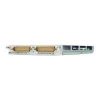
Pinout details for the 50-pin D-Sub male connector on Bank 1 and Bank 2.

34921T Terminal Block Details

Description and diagram of the terminal block for thermocouple measurements.

34922A 70-Channel Armature Multiplexer

34922A Simplified Schematic

Diagram showing the two independent 35-channel 2-wire multiplexer configurations.

34922A D-Sub Connector Pinouts

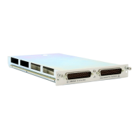
Pinout details for the 78-pin D-Sub male connector on Bank 1 and Bank 2.

34922T Terminal Block Details

Details on terminal blocks for solder or screw connections for the 34922A module.

34923A 40/80-Channel Reed Multiplexer

34923A Configuration Modes

Details on configuring the module for 2-wire, 4-wire, or 1-wire operation.

34923A Simplified Schematic (Two/Four-Wire)

Diagram for 2-wire or 4-wire mode configurations.

34923A D-Sub Connectors (Two/Four-Wire)

Pinout for 2-wire or 4-wire mode on Bank 1 and Bank 2.

34923T Terminal Blocks (Two/Four-Wire)

Details on terminal blocks for 2-wire or 4-wire configurations.

34924A 70-Channel Reed Multiplexer

34924A Simplified Schematic

Diagram illustrating the two independent 35-channel 2-wire multiplexer configurations.

34924A D-Sub Connector Pinouts

Pinout details for the 78-pin D-Sub male connector on Bank 1.

34924T Terminal Block Details

Details on terminal blocks for solder or screw connections for the 34924A module.

34925A 40/80-Channel FET Multiplexer

34925A Configuration Modes

Details on configuring the module for 2-wire, 4-wire, or 1-wire operation.

34925A Simplified Schematic (Two/Four-Wire)

Diagram for 2-wire or 4-wire mode configurations.

34925A D-Sub Connectors (Two/Four-Wire)

Pinout for 2-wire or 4-wire mode on Bank 1.

34925T Terminal Blocks (Two/Four-Wire)

Details on terminal blocks for 2-wire or 4-wire configurations.

Related product manuals