48 Keysight 34921A-34925A Low Frequency Multiplexer Modules User’s Guide
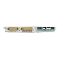
Low Frequency Multiplexer Modules 34925A 40/80-Channel Optically-Isolated FET Multiplexer
Four-Wire Mode
- You may configure the 34925A as a single 20-channel 4-wire MUX. This
configuration requires using neither external wiring nor connecting through
the internal Analog Buses. For 4-wire resistance measurements, the
instrument automatically pairs channel n on Bank 1 (source) with channel
n+20 on Bank 2 (sense) to provide these connections. Four-wire controls
occur only when doing 4-wire measurement operations through the internal
DMM, such as MEASure:FRESistance? or scanning a channel previously
configured as 4-wire.
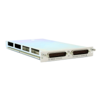
One-Wire Mode
- two independent 40-channel 1-wire MUXes. This configuration requires
neither using external wiring nor connecting through the Analog Bus relays.
- one 80-channel 1-wire MUX. You must use external wiring or connect through
the Analog Bus relays for this configuration.
Interlock Protection
This module is interlock protected, which means whenever the D-sub connector
end of the modules is exposed, the Analog Bus relays immediately open and
disconnect from the Analog Buses. For more information, see “Safety Interlock”
on page 11.
Overvoltage Protection
This module also features high voltage detection (< 100 V) and current limiting
circuitry to protect the FET relays. This circuitry senses current flows from input
overvoltages. These overvoltages may come from either the MUX input or from
the Analog Buses. In addition, each channel is also protected from input
overvoltages with a resistor.
When overvoltage is detected, all relays (Analog Bus and FET) are opened. While
in the overvoltage state, any attempts to close any Analog Bus or FET switch,
results in an error status response from the module.
Once in the overvoltage state, you must restore normal module operation with
one of these actions:
- using the SYSTem:CPON <slot> command. This affects only the module
specified.
Because all bank relays supply only HI signals, you can
apply a LOW signal through COM1 L or COM2 L when you
are making 2-wire resistance measurements in 1-wire
mode.
Artisan Technology Group - Quality Instrumentation ... Guaranteed | (888) 88-SOURCE | www.artisantg.com