Keysight 34921A-34925A Low Frequency Multiplexer Modules User’s Guide 29
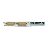
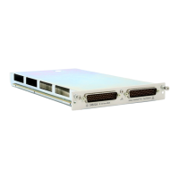
Low Frequency Multiplexer Modules
Two-Wire Mode
You may configure the 34923A as:
- two independent 20-channel 2-wire MUXes. This configuration requires
neither the use of external wiring nor connection through the internal Analog
Buses.
- one 40-channel, 2-wire MUX. For this configuration, you must use external
wiring or connect through the internal Analog Buses.
In 2-wire mode, you can close no more than 20 channels simultaneously due to
power dissipation. Note that there are two 20 channel banks in 2-wire mode.
Each 20 channel bank is further divided into two 10 channel sub-banks in the
control circuitry. These 20 channels are split 10 to a bank. However, note that
Analog Bus relays count half as much as channel relays in that total. For
example, with one Analog Bus relay closed, you can close up to a maximum of 19
channel relays. If you try to close more than the allowed number of channels, you
will receive an error message.
Four-Wire Mode
You may configure the 34923A as a 20-channel 4-wire MUX. This configuration
requires neither external wiring nor connection through the Analog Buses.
For 4-wire resistance measurements, the instrument automatically pairs channel
n on Bank 1 (source) with channel n+20 on Bank 2 (sense) to provide these
connections. Four-wire controls occur only when doing 4-wire measurement
operations through the internal DMM, such as MEASure:FRESistance? or
scanning a channel previously configured as 4-wire.
One-Wire Mode
You may configure the 34923A as:
- two independent 40-channel 1-wire MUXes. This configuration requires
neither external wiring nor connection through the internal Analog Buses.
- one 80-channel 1-wire MUX. You must use external wiring or connect through
the internal Analog Bus for this configuration.
In 1-wire mode, you can close no more than 40 channels simultaneously due to
power dissipation. Note that there are two 40 channel banks in 1-wire mode.
Each 40 channel bank is further divided into two 20 channel sub-banks in the
control circuitry. These channels are split 20 to a bank. For example, with one
Because all bank relays supply only HI signals, you can
apply a LOW signal through COM1 L or COM2 L when you
are making 2-wire resistance measurements in 1-wire
mode.
Artisan Technology Group - Quality Instrumentation ... Guaranteed | (888) 88-SOURCE | www.artisantg.com