Do you have a question about the Keysight E4412A and is the answer not in the manual?
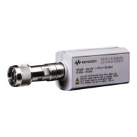
The Keysight E4412A and E4413A are power sensors designed for accurate measurement of continuous wave (CW) microwave power. These sensors are compatible with the newer E44XX-Series power meters, including the E4416A, E4417A, E1416A, or 70100A power meters. They are not compatible with earlier E44XX-Series power meters. The E4412A and E4413A are diode power sensors, offering a wide dynamic range for measurement of CW microwave power levels. The E4412A measures frequencies from 10 MHz to 18 GHz, while the E4413A measures frequencies from 50 MHz to 26.5 GHz. These are high-speed power sensors that incorporate narrow-bandwidth averaging, used in average-power sensors. They support measurement errors with digital, pulse, or other forms of amplitude modulation. Multi-tone signals (containing multiple frequency components) or signals with significant harmonic content (> -45 dBc) may introduce measurement errors at high power levels. The power sensors display CW power in logarithmic (dBm) or linear (Watts or %) measurement units. The E4413A is shipped with a 3.5-mm to Type-N adapter, part number 08485-60005. It's important to note that the E4412A and E4413A power sensors are extremely static-sensitive, so users should not open the power sensor unless they and the power sensor are at a static-free workstation.
The E4412A and E4413A are designed for indoor use and in an area with low condensation. The general environmental requirements for this instrument are:
The E4413A power sensor with adapter has specific S-Parameter specifications:
The power sensors are connected to a power meter via an 11730A sensor cable. The E4412A uses a Type-N (male) connector, and the E4413A uses a 3.5-mm (male) connector. A torque wrench should be used to tighten these connectors: a 3/4-inch open-end wrench and torque to 12 in-lb (135 Ncm) for the Type-N connector, and an 8 in-lb (90 Ncm) for the 3.5-mm connector. Keysight Technologies recommends a one-year calibration cycle for the E4412A and E4413A power sensors.
When operating the power sensor, it's crucial to observe safety precautions. Before connecting the power sensor to other instruments, ensure that all instruments are connected to a protective (earth) ground to prevent electrical shock. The maximum average power is 200 mW (+23 dBm), and the maximum peak power is 200 mW (+23 dBm). The maximum torque at the connector should not exceed 12 in-lb (135 Ncm) for the Type-N connector, or 8 in-lb (90 Ncm) for the 3.5-mm connector. The connector plastic insulator bead can deteriorate when contacted by certain chemicals, so cleaning should be done with appropriate methods.
The E4413A power sensor is fitted with a 3.5 mm (m) connector as standard. To convert the 3.5 mm (m) connector for calibration, an adapter (3.5 mm (f) to Type-N (m)) is included with the power sensor. The 3.5 mm to Type-N adapter is intended for the use of the 1 mW, 50 MHz power reference of the power meter only. Its function as a calibration reference may be compromised if it is used for other purposes. The adapter supplied with a new sensor typically has a loss of < 0.1%. Adapter loss could potentially contribute to absolute power measurement accuracy and needs to be considered.
The system calibration involves setting up the equipment according to a specific configuration, including a Performance Network Analyzer (PNA), adapters, and mechanical calibration kits. The PNA settings include a start frequency of 10 MHz, stop frequency of 100 MHz, 19 points, power of -8 dBm, IF bandwidth of 10 Hz, averaging of 1, sweep time of 1 s, sweep auto true, and smoothing of 0%. The procedure involves extending Port 1 and Port 2 of the PNA, performing port calibrations, and using a wizard for adapter-under-test connection. The firmware will estimate the delay, which should be approximately 0.11 ns.
The DUT measurement involves leaving the adapter-under-test in place and recording the S-Parameter readings (LOG_MAG) for the PNA as dutS11, dutS12, dutS22, and dutS21, comparing them against the typical specifications.
The performance test includes voltage standing wave ratio (VSWR) performance verification and power linearity performance verification.
This verification ensures that the residual offset error is present after zeroing has been performed. This involves connecting the DUT to the power meter, warming up the DUT, connecting to the power meter reference terminal, detaching the DUT from the power meter reference oscillator, launching the Interactive IO, setting the frequency, enabling auto-averaging, changing the power measurement unit, setting the DUT to single trigger mode, reading the noise level, repeating readings, and comparing the calculated mean value to the product datasheet.
A list of replaceable parts is provided, including sensor modules, adapters, chassis parts, shields, and labels. For replacement parts, contact the Keysight Parts Center in Roseville, California.
Troubleshooting information is provided to isolate the power sensor, the cable, or the power meter as the defective component. If an error message 241 or 310 is displayed, it indicates a problem with making a measurement, which might be resolved by replacing the cable or power sensor. Electrostatic discharge will render the power sensor inoperative, so it should only be opened in a static-free environment. The maximum measurable power of a power sensor varies depending on the sensor model. Keysight Technologies' service centers receive a high number of power sensors damaged due to over-powering.
Stable and repeatable measurements require clean and undamaged connectors. Regular cleaning and careful handling are necessary to achieve maximum stability and repeatability. Steps for connector maintenance include selecting the test equipment for the lowest SWR, keeping the cable length as short as possible, using good quality cables, selecting appropriate connectors, keeping connectors clean, measuring (gauging) the connectors regularly, replacing faulty or damaged cables and connectors promptly, not making your own cables, minimizing the number of adapters, using semi-rigid cables for permanently connected cables, following manufacturer's recommendation for minimum bend-radius, fixing the measurement equipment to the bench if possible, not overtightening connectors, not mating dissimilar families, and avoiding temperature extremes.
Cleaning solutions should be non-flammable. A solution of pure isopropyl or ethyl alcohol can be used to clean the connector. The RF connector beads can deteriorate when contacted by hydrocarbon compounds such as acetone, trichloroethylene, carbon tetrachloride, and benzene. The connector should only be cleaned at a static-free workstation. Electrostatic discharge to the center pin of the connector will render the power sensor inoperative. To clean the connector face, use a cotton swab dipped in isopropyl alcohol. If the swab is too big, use a round wooden toothpick wrapped in a lint-free cotton cloth dipped in isopropyl alcohol. Refer to Keysight Application Note 326, Principals of Microwave Connector Care (5954-1566) or Microwave Connector Care (08510-90064) for proper cleaning methods.
To remove the power sensor shell, insert the blade of a screwdriver between the plastic shells at the rear of the power sensor. Pry alternately at both sides of the connector J1 until the plastic shells are apart. Remove the shells and the magnetic shields.
To reassemble, replace the magnetic shields and the plastic shells as shown in Figure 1-9. Snap the plastic shells together.
Adjustments are typically required annually, usually after a performance verification indicates parameters are out of specification. Performance verification must be completed after any repairs that may have altered the characteristics of the E-Series E4412A and E4413A power sensors. The sensors can be returned to Keysight for adjustments.
| Brand | Keysight |
|---|---|
| Model | E4412A |
| Category | Accessories |
| Language | English |