12 Installation Note N9030-90058
Option EXM, External Mixing Upgrade Kit
Front Frame Assembly Removal
NOTE Make sure any connectors on the front panel are removed.
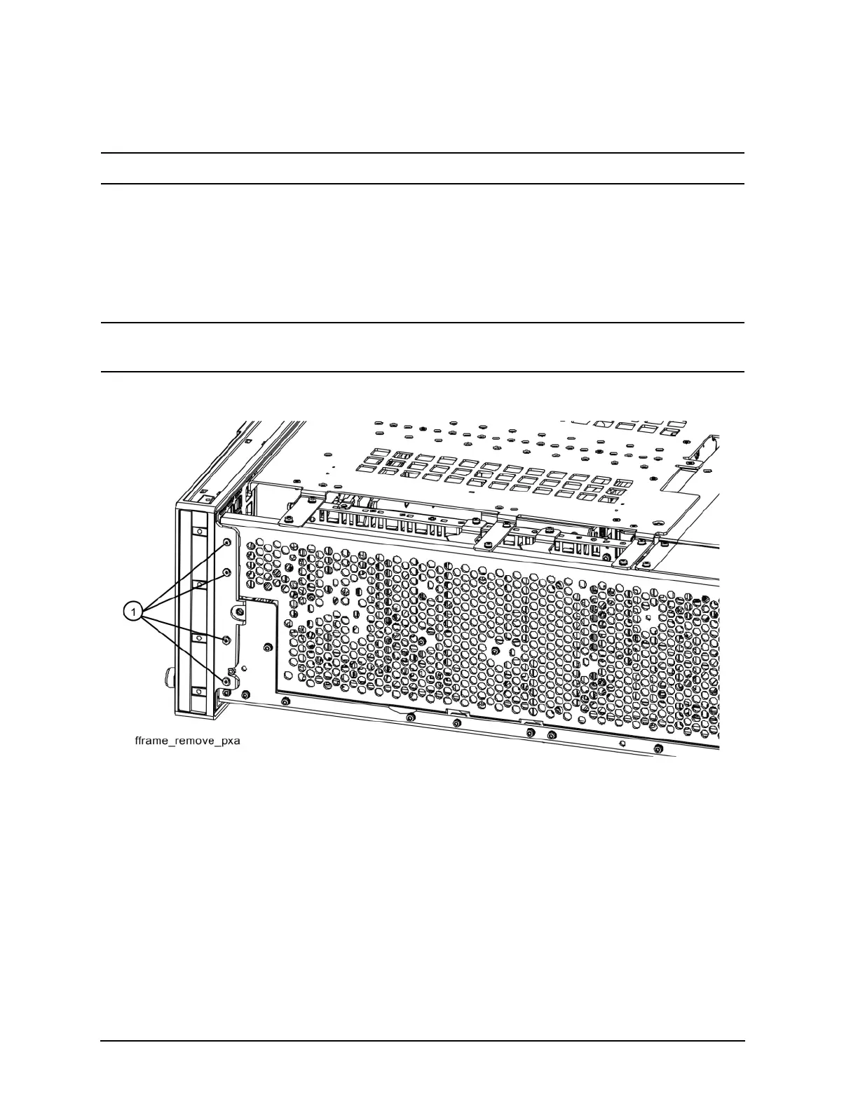
1. Refer to Figure 4. Using the T-10 driver, remove the eight screws (1) (0515-1035), four on each
side, to detach the Front Frame Assembly from the chassis.
2. Refer to Figure 5. Pull the Front Frame Assembly carefully away from the chassis. Remove the
ribbon cable W1 from the motherboard. The cable has locking tabs on each side, pinch and pull to
release.
NOTE W1 may have locking springs on each side. Depress the spring on each side of the
connector to remove from the motherboard.
Figure 4 Front Frame Removal
 Loading...


