54
Line Impedance Stabilization Networks (LISN)
LISN Operation
LISN Operation
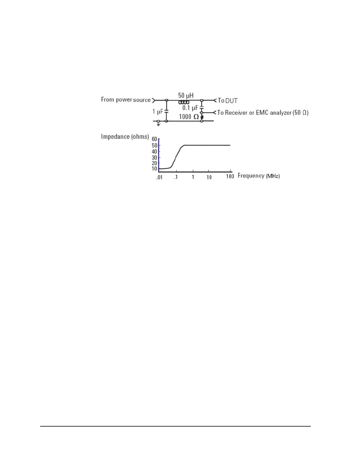
The following graphic shows a typical LISN circuit diagram for one side of the line
relative to earth ground. The chart represents the impedance of the DUT port versus
frequency.
The 1 μF in combination with the 50 μH inductor is the filter that isolates the mains
from the DUT. The 50 μH inductor isolates the noise generated by the DUT from the
mains. The 0.1 μF couples the noise generated by the DUT to the EMI Receiver. At
frequencies above 150 kHz, the DUT signals are presented with a 50Ω impedance.

 Loading...


