Keystone Boilers and Water Heaters
Page 29
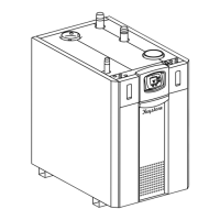
Figure 23. DHW Piping, Two Heaters, One Vertical Tank.
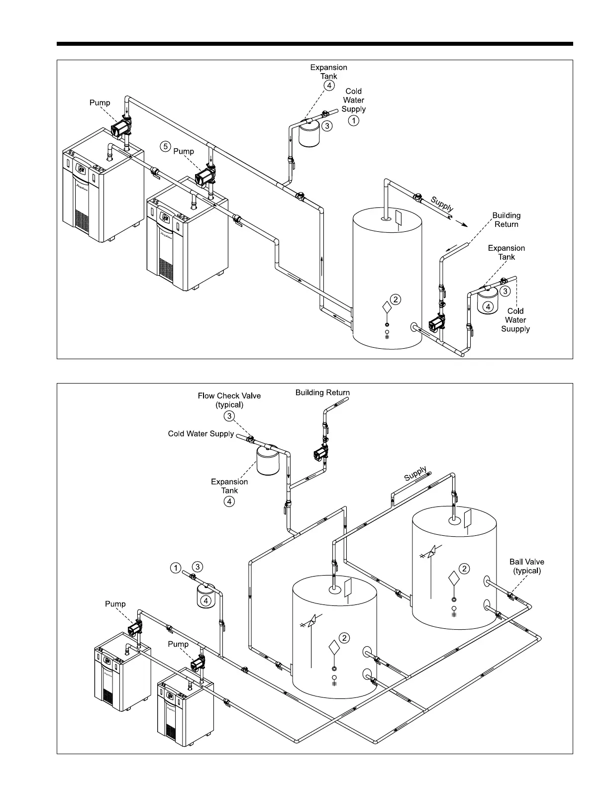
Figure 24. DHW Piping, Two Heaters, Two Vertical Tanks.
1. Optional CWMU & Recirc. line location.
2. Locate KW DHW sensor or remote aquastat
well in lower 1/3 of tank.
3. Back flow preventer may be required - check
local codes.
4. Thermal expansion tank may be required -
check local codes.
5. Caution: Pump sizing must be based opon
water hardness at job site.
6. Pipe size between Keystone and storage tank
must be the same as the Keystone heater.
7. Size pump based on a maximum delta T of 15
degrees at full input rate.
WARNING: THIS DRAWING SHOWS
SUGGESTED PIPING CONFIGURATION AND
VALVING. CHECK WITH LOCAL CODES AND
ORDINANCES FOR ADDITIONAL REQUIREMENTS.
NOTES:
1. Optional CWMU & Recirc.
line location.
2. Locate KW DHW sensor
or remote aquastat well
in lower 1/3 of tank.
3. Back flow preventer may be
required - check local codes.
4. Thermal expansion tank may be
required - check local codes.
5. Caution: Pump sizing must
be based opon water
hardness at job site.
6. Pipe size between Keystone and
storage tank must be the same as
the Keystone heater.
7. Size pump based on a maximum
delta T of 15 degrees at
full input rate.
WARNING: THIS DRAWING SHOWS
SUGGESTED PIPING CONFIGURATION AND
VALVING. CHECK WITH LOCAL CODES AND
ORDINANCES FOR ADDITIONAL REQUIREMENTS.
NOTES: