EasyManua.ls Logo

Kia 1U056 ADU00 User Manual

Kia 1U056 ADU00
25 pages
To Next Page IconTo Next Page
Page #1 background imageLoading...
Page #1 background image
Revision Date
4/22/2013
Page 1 of 25
Vehicle Model Sorento (Key Start) Accessory Remote Engine Start
Model Year 2014 ~ Dif culty ( B )
Part No. 1U056 ADU00
KIA Genuine Accessories
Instruction Symbols / De nitions
Note: Dif culty stated above re ects the minimum level of expertise required to install the accessory
( A ) Customer ( B ) Dealer Technician ( C ) Master Technician
Denotes warnings that may lead to
serious physical injury or vehicle
damage.
Denotes cautions to be taken to avoid
physical injury or electronic component
damage.
Denotes cautions to be taken to avoid
vehicle and component damage.
Denotes quality processes to be
checked prior to moving to the
next step.
Denotes speci c tools that are neces-
sary to complete the step.
Denotes instructional steps
necessary to complete the
process.
Denotes safety equipment required to be used
such as a mask, goggles, rubber
gloves, and hearing protection.
N
O
T
E
Notes to the Installer:
Read the entire installation manual prior to beginning the installation of the
accessory.
Factory wire harness colors are subject to change, please use the speci ed pin
# in the harness connector to identify the correct wire for T-Tap installation.
Ensure that the vehicle is properly protected in the area that the accessory is to
be installed.
To prevent vehicle damage, never place tools on top of painted surfaces, seats,
dash pad, console or oor carpet / mat.
Always wear appropriate safety gear to include gloves and eye protection when
required.
To prevent stress on the remote start wire harness, ensure the tilt/telescopic
steering column is fully extended, if equipped.
Ensure the transportation fuse is properly installed before performing the
function check on page 17.
Technical Support
For Authorized Dealers - (800) 667-5176
Hours: 9:00 a.m. - 5:30 p.m. EST Monday - Friday
Basic Required Hand Tools
Mask
Rubber Gloves Hearing Protection
Goggles
Ensure vehicle is equipped with automatic transmission, power door locks
and power windows. If the vehicle is not equipped with these options, do
not proceed. Ensure vehicle does NOT have SMART KEY.
!
P/N: 4280516, Rev. A
Ratchet
#2 Phillips
Screwdriver
Trim Tool
Wire Cutter
Pliers
10 mm Socket
Alcohol Cleaner /
Clean Cloth
Extension
Torque Wrench
Tape Measure
Question and Answer IconNeed help?

Do you have a question about the Kia 1U056 ADU00 and is the answer not in the manual?

Kia 1U056 ADU00 Specifications

General IconGeneral
BrandKia
Model1U056 ADU00
CategoryRemote Starter
LanguageEnglish

Summary

Instruction Symbols / Definitions

Warning Symbols

Indicates warnings for potential serious physical injury or vehicle damage.

Caution Symbols

Indicates cautions to avoid physical injury or electronic component damage.

Note Symbols

Indicates instructional steps or quality processes to be checked.

Safety Equipment

Highlights required safety equipment like masks, goggles, and gloves.

Basic Required Hand Tools

Required Tools List

Lists essential hand tools like ratchets, sockets, screwdrivers, and pliers for installation.

Notes to the Installer

Installation Guidance and Precautions

Provides crucial installation guidance, including vehicle protection and safety gear usage.

Accessory Components Overview

Component Identification

Identifies and lists all included components with their part numbers and quantities.

Hardware Kit Contents

Details the specific items included within the hardware kit for installation.

T-Tap Installation Procedure

Correct T-Tap Placement

Illustrates correct and incorrect methods for placing T-Taps on vehicle wires.

Connector Handling

Provides guidance on safely disconnecting and locking electrical connectors.

Wire Color Identification

Explains how to identify wire colors, distinguishing between base color and stripe color.

Vehicle Preparation

Initial Vehicle Checks

Checks vehicle compatibility, transmission type, and key system before proceeding.

Steering Column Adjustment

Ensures the steering column is fully extended and locked before installation.

Installation Steps: Dash Preparation

Fuse Box and Warning Label

Covers preparing the fuse box and mounting the warning label.

Dash Panel Removal

Guides removal of dash panels, access covers, and connectors.

Installation Steps: Interior Panel Removal

Knee Bolster and Steering Column Shroud

Details removal of knee bolster, steering column shroud, and related components.

A-Pillar Trim Panel

Instructs on removing the driver's side 'A' pillar trim panel and access cover.

Installation Steps: Antenna Mounting

Antenna Preparation and Mounting

Covers cleaning the windshield and mounting the dipole antenna.

Antenna Cable Routing

Details wrapping and routing the antenna cable up to the headliner.

Installation Steps: Cable Securing and Module Connection

Securing Antenna Cable

Secures the antenna cable with wire ties, emphasizing air bag safety.

Module Connector Installation

Connects transmitters and plugs in remote start module connectors.

Installation Steps: Control Module Mounting

Securing Remote Start Module

Mounts the remote start control module to the vehicle dash wall.

Installation Steps: Ignition and Key-In-Sense Connections

Ignition Switch Wiring

Routes ignition connectors and connects them to the factory M15 ignition switch.

Key-In-Sense Wiring

Routes and connects key-in-sense connectors to the factory M37 connector.

Installation Steps: Brake Switch Connections

Brake Switch Wiring

Routes and connects brake switch connectors to the factory E41 connector.

Installation Steps: Fuse Panel Connections

Fuse Panel Wiring

Routes ground wire and 26-pin connectors to the fuse panel and ground bolt.

Installation Steps: Fuse Panel Reinstallation and T-Tap

Fuse Panel Reinstallation

Reinstalls the fuse panel after T-Tap connection.

T-Tap Connection to Brown Wire

Makes a T-Tap connection to the brown wire at pin #35 of the 38-pin connector.

Installation Steps: I/P-D Connector Connections

I/P-D Connector Wiring

Routes and connects 24-pin connectors to the factory 24-pin I/P-D connector.

Installation Steps: I/P-K Connector Connections

I/P-K Connector Wiring

Routes and connects 26-pin connectors to the factory 26-pin I/P-K connector.

Installation Steps: Final Harness Securing

Harness Verification and Securing

Verifies connections, attaches programming button, and secures harness with wire ties.

Installation Steps: Vehicle Power-Up

Final Checks and Vehicle Start

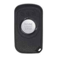
Verifies connections, turns ignition, reconnects battery, and starts vehicle.

Function Check

Remote Engine Start Check

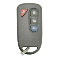
Tests remote engine start feature using the transmitter.

Door Unlock and Light Checks

Verifies driver door unlock, dome lights, and all door unlocks.

Safety Switch Checks

Tests hood, tailgate safety switches and brake pedal safety.

Transmitter Feature Checks

Tests car find, panic, quick stop, and remote engine stop functions.

Reinstallation Steps: Interior Panels

A-Pillar and Access Panel Reassembly

Reinstalls A-pillar trim, access cover, and related components.

Steering Column and Knee Bolster Reassembly

Reinstalls steering column shroud and knee bolster panel.

Reinstallation Steps: Dash and Manuals

Dash Panel and Connector Reassembly

Reinstalls dash panels, connectors, and fuse panel access cover.

Storing Owner's Guides

Places Owner's Guide and Quick Reference Guide into the glove box.

Troubleshooting Overview

Accessing DNA Card and Fuse Positions

Details accessing the DNA card and correct fuse/jumper placements.

Troubleshooting: System Operation

Door Lock, Light, and Range Issues

Addresses issues with door locks, lights, and poor operating range.

Parking Light and Horn Issues

Troubleshoots parking lights not flashing and burglar horn problems.

Troubleshooting: Engine and Feature Performance

Engine Start and Running Issues

Resolves engine start failures, stall conditions, and headlight behavior.

HVAC and Safety Input Issues

Troubleshoots HVAC fan operation and safety input related problems.

Transmitter Programming and Battery Maintenance

Transmitter Programming Procedure

Step-by-step guide for programming new transmitters.

Transmitter Battery Test Procedure

Instructions for testing and replacing transmitter batteries.

Wiring Diagrams

Remote Start Wiring Diagram - Page 1

Diagram showing wiring connections for the remote start system (Part 1).

Remote Start Wiring Diagram - Page 2

Diagram showing wiring connections for the remote start system (Part 2).

Related product manuals