5
INSTALLATION
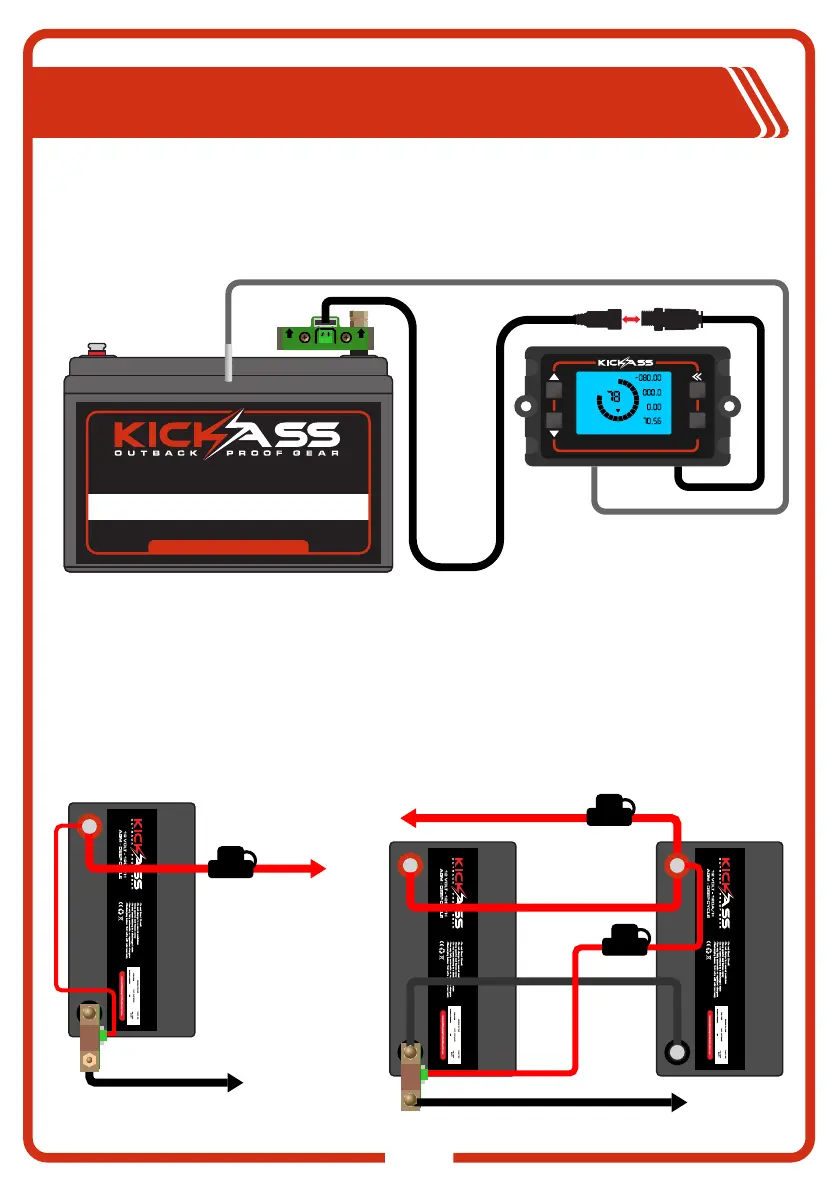
Connecting Display to the Shunt Assembly
The Battery Monitor Display can be connected to the Shunt, with the provided cables. To do this
firstly connect the data cable to the shunt assembly by plugging in the small white 5 pin connector,
now connect the two round black connectors to join the display and shunt together. The Temperature
sensors can now be run to the battery or desired location for ambient temperature reading.
OK
%
CAP
FCV
LCA
ZCV
POV
ATT
CURRENT
VOLTAGE
TEMP
TIME REMAINING
AH
V
°C
H
B-
P-
B+ B+
12 VOLT - 120A/H
www.kickassproducts.com.au
AGM - DEEP CYCLE
VISI T OUR WEB SITE FOR M ORE DETAIL S
Connecting Loads and Chargers to Shunt Assembly
When connecting loads and chargers to the battery using the Shunt, system negative connections
must be connected to the P- side of the Shunt Assembly. No negative connections should be made
directly to the battery terminal as this will cause the battery monitor to provide false readings. When
wiring batteries in parallel, ensure the correct connection configuration is used. Please refer to
diagram.
CAUTION: Use a suitably rated Fuse/Circuit breaker for all loads. When using the shunt in
theparallel configuration, we recommend using an in line fuse for the B+ Wire. See diagram.
TO ELECTRICAL
EQUIPMENT AND
CHARGING UNIT
SINGLE BATTERY
BATTERY A
PARALLEL BATTERIES
BATTERY A
TO ELECTRICAL EQUIPMENT
AND CHARGING UNIT
BATTERY B
TEMP SENSOR
FUSE
FUSE
FUSE