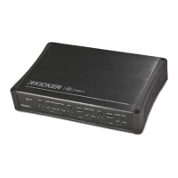
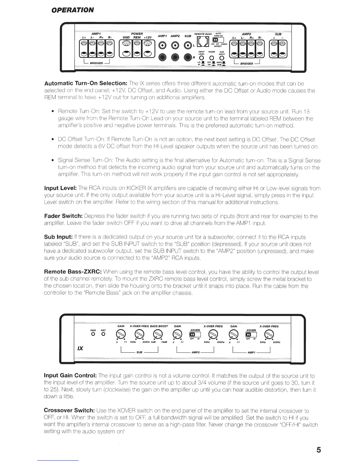
OPERATION
AMP1
POWER
AMPf
AMP
2
SUB
REMOTE
BASS
T~;~N
AMP2
SUB
~
~
0
L
o
·~-
l;r~i.I;I;J
· -
~
~
••
•
R
~
0
iS'
eJ eJ
e>
e>
bbl
L
BRIDGED
_j
lO.
OFF.
AMP
2
•
L
BRIDGED
_j
HI
ON~
SUB_._
Automatic Turn-On
Selection:
The
IX
series
o
ffer
·s
three different automatic turn-on modes that can be
selected
on
the end panel; +
12V,
DC
Offset, and Audio. Using either the DC Offset or Audio mode causes the
REM
terminal to have + 12V out for
turn1ng
on additional amplifiers.
•
Rem
ote
Turn-On:
Set the
sw
itch
to+
12V to use the remote turn-on
le
ad from your source unit.
Run
18
gauge w
ire
f
ro
m
th
e Remote
Turn-On
Lead
on
your source unit to the terminal
la
beled
REM
between the
amplifier's positive and negative power terminals. This
is
the preferred automatic turn-on method.
• DC Offset Turn-On:
If
Remote Turn-On
is
not
an
option, the next best setting
is
DC
Offset. The
DC Offset
mode detects a 6V DC
offset from the
HI-Level
speaker outputs when the source unit has been turned
on.
•
Signal Sense Turn-On:
Th
e Audio setting is the f
ina
l alternative for Automatic turn-on.
Thi
s
is
a Signal Sense
turn-on method
th
at detects the incom
in
g audio signal from your source
un
it and automatically turns on the
amplifi
er.
Th
is turn-on method w
ill
not work properly
if
the input gain control
is
not set appropriately.
Input Level:
The
RCA
inputs on
KICKER
IX
amplifiers
are
capable of receiving either
Hi
or Low-level signals from
your source unit.
If
the only output available from your source unit
is
a Hi-Level signal, simply press
in
the
Input
Level sw
it
ch on the ampl
ifier.
Refer to the wiring section of this manual for additional instructions.
Fader
Switch: Depress the fader
sw
it
ch
if
you are running t
wo
sets of inputs (front and rear for example) to the
amplifier. Lea
ve
the fader switch
OFF
if
you want to drive
all
channe
ls
from the
AMP1
input.
Sub Input:
If
there
is
a dedicated output
on
your source unit for a subwoofer, connect
it
to the RCA
inputs
labeled
"SUB", and set the SUB
INPUT
switch to the
"SUB" position (depressed).
If
your source unit does
not
have a dedicated subwoofer output, set the SUB
INPUT
switch to the
"AMP2"
position (unpressed), and make
sure your audio source
is
connected to the
"AM
P2
" RCA
inputs.
Remote Bass-ZXRC:
When using the remote bass
level
control, you have the ability to control the output level
of the sub
channel
remotely.
To
mount the
ZXRC
remote bass level control, simply screw the metal bracket to
the chosen
lo
cation, then slide the housing onto the bracket until
it
snaps into place.
Run
the cable from the
controller to the "Remote
Bass"
Jack
on
the amplifier chassis.
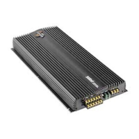
GAIN
X-OVER
FREQ BASS BOOST
GAIN
X-OVERFREQ
GAIN
X-OVERFREQ
PWR
PRT
~
~
~
~
X
OVER
~
~
X
OVER
~
0 0
go
go
OFF
HI
OFF
HI
0
11
50Hz
200Hz
OdB
18dB
0
11
50Hz
200Hz
0
11
50Hz
200Hz
IX
L_SUB__j
L_AMP2_j
L_AMP1_j
Input
Gain
Control:
The input gain control
is
not a volume control.
It
matches the output of the source unit to
the input level of the amplifi
er.
Turn
the source unit up to about
3/4
volume
(if
the source unit goes to
30,
turn
it
to 25). Next, slowly turn (clockwise) the gain on the amplifier up until you can hear audible distortion, then turn
it
down a little.
Crossover
Switch: Use the
XOVER
switch on the end panel of the amplifier to set the internal crossover to
OFF,
or
HI.
When the switch
is
set to
OFF,
a
full
bandwidth signal
will
be amplified. Set the switch to
HI
if
you
want the amplifier's internal crossover to serve
as
a high-pass filter. Never change the crossover
"OFF/HI"
switch
setting with the audio system on!
5
 Loading...