Do you have a question about the Kicker KX350.4 and is the answer not in the manual?
Record purchase information and attach the original sales receipt for future reference.
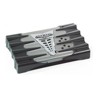
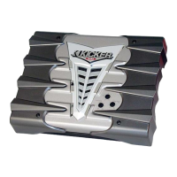
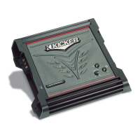
Welcome message highlighting the advanced technology and performance of your new Kicker amplifier.
Class A/B stable into 2 ohm stereo/4 ohm mono; SORT circuitry protects against various faults.
Efficient MOSFET power supply; variable bass boost up to 18dB at 40Hz for enhanced low-end.
Supports high & low level inputs; built-in variable crossover (50-200Hz).
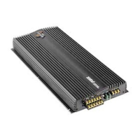
Custom gold plated connectors for optimal power transfer; SAMS for simultaneous stereo/mono use.
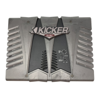
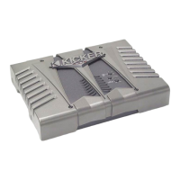
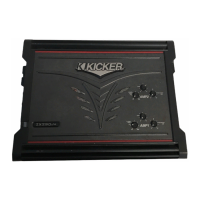
Features removable EndKaps for wiring concealment and a remote bass level control.
Two-year warranty provided when purchased from an authorized KICKER dealer.
Choose a structurally sound area, ensuring no damage to vehicle lines or components.
Select a location allowing adequate airflow to prevent overheating, especially in enclosed spaces.
Remove the amplifier EndKap using the 3mm allen wrench for access to mounting holes.
Drill pilot holes with a 7/64" bit and use #8 screws to mount the amplifier securely.
Connect using low-level RCA inputs (preferred) or high-level speaker inputs.
Properly connect ground to chassis and install a fuse near the battery for the power wire.
Route RCA cables away from power wiring, using twisted pairs and 90-degree crossings to minimize noise.
Consult the chart for appropriate wire size and fuse rating based on the amplifier model.
Use RCA dummy plugs in AMP 2 inputs with High Level inputs for correct fader operation.
Diagram illustrating stereo operation at a minimum 2-ohm impedance per channel.
Diagram showing bridged mono operation at a minimum 4-ohm impedance.
Diagram for combined stereo (2-ohm) and bridged (4-ohm) operation.
Setting the internal crossover for full range, subwoofer (LO), or speaker (HI) output.
Matching head unit output to amplifier input; adjust for optimal performance without clipping.
Fine-tuning crossover frequency and adjusting bass boost for desired sound characteristics.
Instructions for mounting the remote bass level controller and connecting it to the amplifier.
Detailed RMS power ratings for all models across various impedance and THD+N conditions.
Includes dimensions, frequency response, input sensitivity, signal-to-noise ratio, and crossover details.
Explanation of CEA-2006 power and signal-to-noise ratio standards for each model.
Understanding the meaning of green and red LEDs for amplifier status and protection.
Troubleshooting steps for no audio output, covering protection circuits and power issues.
Resolving issues where only one channel is producing sound.
Tips for resolving alternator noise and improving stereo image or bass response.
Important safety warnings regarding proper jumper cable connections to prevent damage.
Guidance on seeking assistance from Authorized Dealers or Kicker Technical Services.
Details the warranty period (3 months/2 years) and conditions for defects in material and workmanship.
Instructions for returning defective merchandise for repair or replacement.
Lists conditions and damages not covered by the manufacturer's warranty.
Information on Kicker's goal for electronics service turnaround time.
| Channels | 4 |
|---|---|
| Frequency Response | 20 Hz - 20 kHz |
| Signal to Noise Ratio | > 95 dB |
| Fuse Rating | 30A |
| Input Voltage | 14.4V |
| Crossover | High Pass / Low Pass |