Dual Zone Digital Location Control Unit Installation and Operation Manual 8
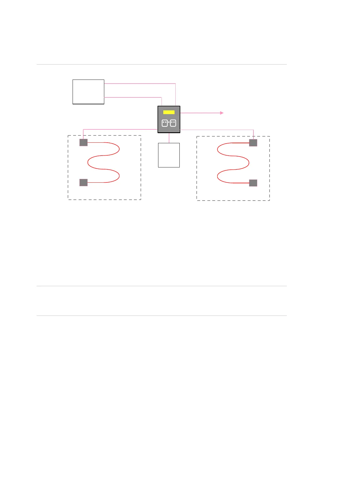
Protection of two risk areas with two sensor cables through one control
unit
Figure 3: Protection of two risk areas with two sensor cables through one control unit
This setup provides two independent zones covering two separate risk areas with
each zone reporting its own status to the main fire alarm system.
The sensor cables connected to each zone can have different alarm
temperatures and different protective outer sheaths to suit the area they are
protecting.
To report to the main fire alarm system, two separate conventional detection
circuits or two addressable monitoring interfaces are required to monitor the
status of each independent zone.
Caution: As the system uses one control unit, the total combined area coverage
of both Digital LHD zones cannot exceed the maximum detection zone size as
defined by local standards (refer to your local standards).
sensor cable
sensor cable
PSU
control panel
zone 1
zone 2
 Loading...