Dual Zone Digital Location Control Unit Installation and Operation Manual 6
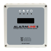
Figure 2: Alarmline II Digital LHD system
Technical specifications
12-36 VDC (nominal 24 VDC)
Standby
Alarm
<7 mA at 24 VDC
<15 mA at 12 VDC
<5 mA at 36 VDC
<40 mA at 24 VDC
<23 mA at 12 VDC
<15 mA at 36 VDC
s
Spacing
Current rating
Cable size
5 mm rising clamp
16 A
0.08 to 4 mm² (28 AWG to 11 AWG)
nputs
Number of zone inputs
Zone length
End-of-line resistor
Short circuit current
Voltage
Ground fault impedance
2 supervised inputs [1]
1 m (3.28 ft.) min. to 3000 m (10,000 ft.) max.
1 kΩ
0.5 mA
5 V max.
0 Ω
rm outputs
Number of alarm outputs
Current rating
Switching power
2 form C volt-free relay contacts (1 per zone)
2A at 30 VAC/42.4 VDC
60 W, 62.5 VA
Number of fault outputs
Voltage
Current
Power dissipation
2 opto-isolated phototransistor outputs (1 per zone)
35 VDC max.
80 mA max.
150 mW max.
Two-wire RS-485 Modbus RTU
[1] For up to two class B zones of Alarmline II Digital Sensor Cable
Sensor cable
Sensor cable
24 VDC
PSU
Interposing cable (Optional)
Interposing cable (Optional)
Fire alarm
control panel
Zone 2
RS-485 Modbus output
 Loading...