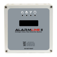
13 Dual Zone Digital Location Control Unit Installation and Operation Manual
Terminal connections
The control unit is provided with a number of fixed terminal connections to enable
external wiring.
Terminal connections are provided for power supply, LHD zones, zone alarms,
zone faults, and Modbus. See the table below for more information on each.
Table 1: Terminal connections
Description
Polarity conscious positive and negative terminals to connect an
external power supply (operating voltage range of 12 to 36 VDC).
Supervised input to connect a zone of sensor cable. The cable can be
connected directly or via an interposing cable.
The input requires a 1 kΩ EOL monitoring resistor.
Supervised input to connect a zone of sensor cable. The cable can be
connected directly or via an interposing cable.
The input requires a 1 kΩ EOL monitoring resistor.
Volt-free changeover contacts to signal a fire condition on LHD ZONE
1 to the main fire alarm system. Three terminals are provided: C
(Common), NO (Normally Open), and NC (Normally Closed).
In normal operation there is continuity between the C and NC
terminals. In an alarm condition on zone 1 the relay contacts switch to
provide continuity between C and NO.
Volt-free changeover contacts to signal a fire condition on LHD ZONE
2 to the main fire alarm system. Three terminals are provided: C
(Common), NO (Normally Open), and NC (Normally Closed).
In normal operation there is continuity between the C and NC
terminals. In an alarm condition on zone 2 the relay contacts switch to
provide continuity between C and NO.
An opto-isolated phototransistor output that
changes state when a fault
condition occurs on LHD ZONE 1. The output is failsafe: it is active
when the unit is powered and de-activates when a fault condition
occurs.
A failsafe fault ensures that a fault will be transmitted to the main fire
alarm system in the event of a power failure.
An opto-isolated phototransistor output that changes state when a fault
condition occurs on LHD ZONE 2. The output is failsafe: it is active
when the unit is powered and de-activates when a fault condition
occurs.
A failsafe fault ensures that a fault will be transmitted to the main fire
alarm system in the event of a power failure.
RTU A two-wire RS-485 Modbus output. This can output the status of each
zone to third party control equipment or software.

 Loading...